banner

Blog

Home

Blog

  • When Bending Space Gets Narrow, Sash Punches Find the Way
    Sep 23, 2026
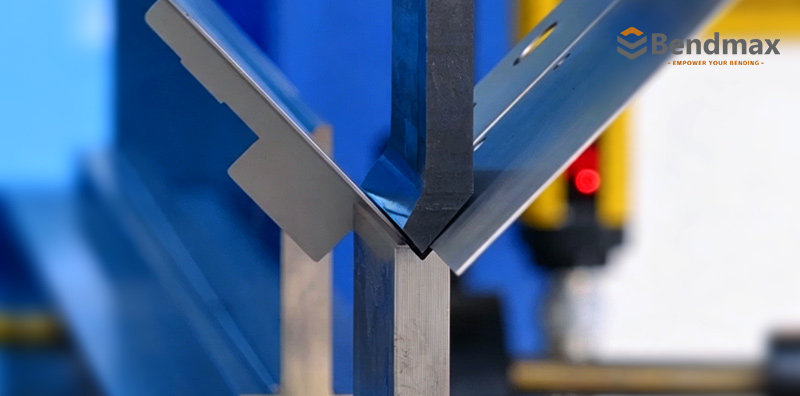
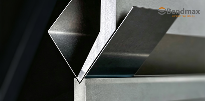
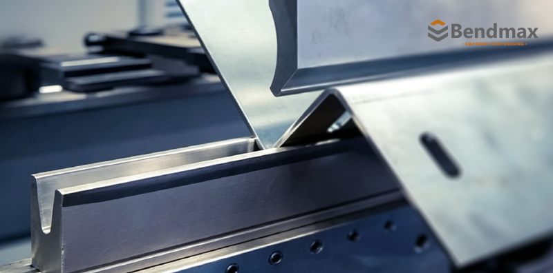
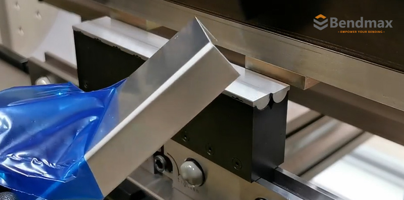
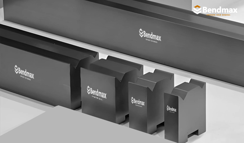
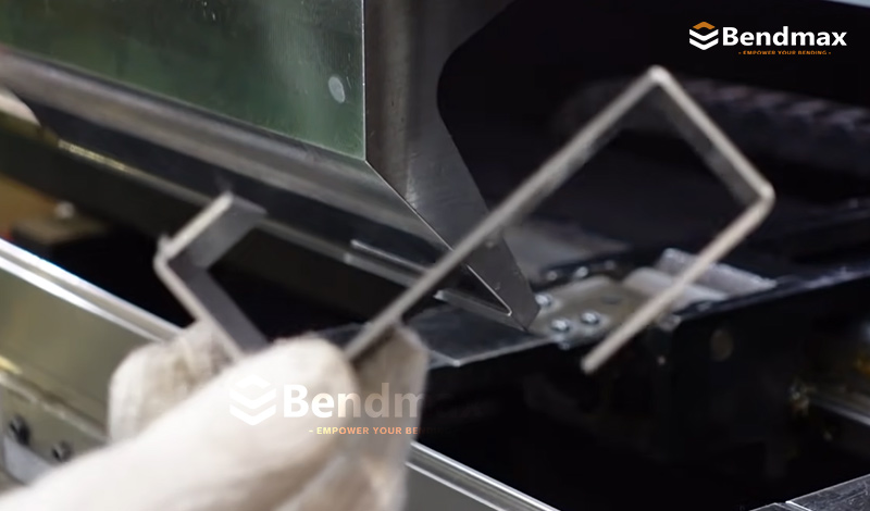
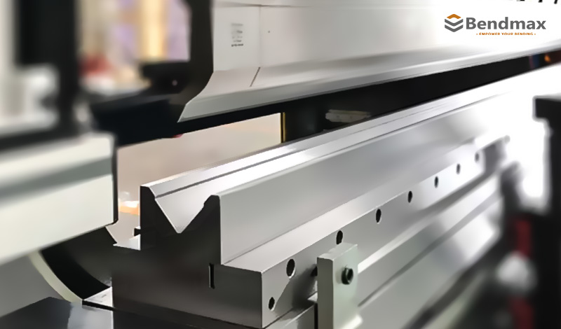
        Sash Punch: A Narrow Standard Punch for Tight Bending Areas   When Bending Space Gets Narrow, Sash Punches Find the Way How Sash Punch Geometry Improves Access Around Corners, Door Frames and Window Profiles   In the previous articles of the Bendmax Common Press Brake Tools Series, we introduced the Standard Punch for everyday bending and the Gooseneck Punch for applications requiring additional clearance. This time, we look at another practical type of standard press brake punch: the Sash Punch. A Sash Punch has a narrow body and an angled, inward-facing tip. This compact geometry allows the punch to reach bending areas where a conventional wider punch may interfere with the workpiece.   What Is a Sash Punch?   A Sash Punch is a type of narrow press brake punch used for bending sheet metal in tight or restricted areas. Its narrow body and angled tip make it suitable for applications such as: •    Door jambs and door frames •    Window frames and sash profiles •    Narrow sheet metal sections •    Corner bending •    Small return flanges •    Architectural metalwork •    Bending around restricted profiles Although it has a distinctive shape, a Sash Punch is not necessarily a special forming tool. It is generally considered a specialized version of a Standard Punch, designed mainly to improve access in narrow bending areas.         How Does a Sash Punch Work?   During bending, the narrow punch body reduces interference between the tool and the workpiece. Its angled tip helps the punch reach the required bend line and work around nearby corners or flanges. The basic process is: The sheet metal is positioned on the lower die. The angled punch tip contacts the material. The sheet forms around the punch and die. The narrow punch profile provides improved access around restricted areas. The required bend is completed with less tool interference. The final bending result still depends on the punch angle, nose radius, die opening, material thickness and bending depth.   Sash Punch vs. Standard Punch     Feature Standard Punch Sash Punch Main purpose General-purpose bending Bending in narrow or restricted areas Body design Conventional wider body Narrow body with angled tip Main advantage Versatility and strength Better access around corners Typical applications General sheet metal parts Door frames, window frames and narrow profiles Tool selection Suitable for common bends Suitable when punch access is limited   A Standard Punch is the normal choice for general bending. A Sash Punch becomes useful when the workpiece geometry requires a narrower tool profile.   Sash Punch vs. Gooseneck Punch   Sash Punches and Gooseneck Punches solve different problems. •   Standard Punch: Used for general-purpose bending. •   Sash Punch: Provides better access in narrow spaces and around corners. •   Gooseneck Punch: Provides additional clearance for deep boxes, U-profiles and return flanges. In simple terms: A Sash Punch is designed for narrow access, while a Gooseneck Punch is designed for deeper clearance. The correct choice depends on the shape and position of the workpiece rather than the punch name alone.   Main Advantages of a Sash Punch   A suitable Sash Punch can provide: Better access to narrow bending areas Reduced interference around corners Improved flexibility for door and window frame production More convenient bending of narrow profiles Consistent results in repeated production Compatibility with different material types, including carbon steel, stainless steel and aluminum However, the actual performance depends on the tooling material, heat treatment, dimensions, machine capacity and application requirements. How to Choose the Right Sash Punch   Before selecting a Sash Punch, check the following information: Workpiece drawing or sample Material type and thickness Required bending angle Inside bend radius Flange width and profile depth Available clearance around the bend Matching lower die Press brake tooling system Machine tonnage and bending length The narrowest punch is not always the best choice. The tool must still provide sufficient strength and stability for the required bending load.  Sash Punches from Bendmax   Bendmax manufactures press brake punches and dies for standard and specialized bending applications. Our Sash Punch solutions are designed for narrow-profile bending, corner access and applications such as door and window frame production. Depending on the machine and workpiece requirements, tooling can be supplied in different dimensions, materials and compatible press brake systems. For a suitable recommendation, customers can provide: Part drawings Material and thickness Bending angle Required inside radius Machine model Tooling system Required punch length Bendmax can then evaluate the working profile and recommend suitable tooling for the application.   A Sash Punch is a practical type of narrow Standard Punch. Its narrow body and angled tip provide better access in restricted bending areas, especially around corners, door frames, window frames and narrow sheet metal profiles. It is not mainly designed for deep-box clearance like a Gooseneck Punch. Its main purpose is to reach narrow bending areas where a conventional Standard Punch may interfere. Standard Punches provide general versatility. Gooseneck Punches create deeper clearance. Sash Punches improve access in narrow bending areas.     The FAQs 1. What materials can be bent with a Sash Punch? Sash Punches can be used for common sheet metals such as carbon steel, stainless steel and aluminum. The suitable material thickness and bending load depend on the punch, die opening and machine capacity.   2. What press brake tooling systems are compatible with Sash Punches? Sash Punches can be manufactured for different press brake tooling systems, including Amada, WILA, Trumpf, LVD and Bystronic-style systems, depending on the required interface and machine configuration.   3. Can a Sash Punch be used for short flanges and narrow profiles?   Yes. Its slim body and angled working profile can provide better access when bending short flanges, narrow sections and profiles close to corners, where a conventional punch may have limited access.   4. What Sash Punch specifications should I check before ordering?   Important specifications include punch angle, nose radius, tool height, length, tooling system, material, required clearance and maximum load. The workpiece dimensions and bending sequence should also be considered.   5. Can Bendmax manufacture Sash Punches in custom sizes?   Yes. Bendmax can manufacture Sash Punches according to drawings, samples or specified dimensions. Custom angles, heights, radii, lengths and tooling interfaces can be evaluated according to the application.   6. How can I select the correct Sash Punch for my application?   Provide the material, thickness, bend angle, inside radius, flange dimensions, machine model and tooling system. A part drawing or photo is especially helpful for checking clearance and selecting the appropriate punch and die combination.   7. Can a Sash Punch be used with my existing press brake die?   In many cases, yes, provided the punch and die are compatible in tooling system, working angle, radius and forming requirements. The existing die opening should also be checked against the material thickness and required bend radius. Bendmax can help verify the tooling combination before ordering. Continue Your Bending Journey Product Details Learn more about this tooling, specifications and compatibility.                                       → Explore the Product: Sash Punch                       Related Solutions See related applications, bending methods and tooling discussions.                                       → Explore Solutions & Discussions                       Need a Price? Tell us your requirements and get a tooling recommendation and quotation.                                         → Request a Quote: Talk to Our Tooling Engineers                           Continue the Bendmax Tooling Series Next: When Narrow Access Is Not the Problem, Acute Punches Take the Angle Further How Acute Angle Punch Geometry Creates Sharp Bends, Supports Overbending and Prepares Parts for Hemming   In the next article, we will move from tool access to bend angle. A Sash Punch helps the tool reach restricted areas around corners, frames and narrow profiles. But sometimes the challenge is not whether the punch can reach the bending position—it is how far the sheet needs to be formed. When the required included angle becomes significantly smaller than a conventional 85° or 90° bending setup can efficiently produce, an Acute Angle Punch provides a different solution. We will explore why acute punches are commonly designed with angles such as 30°, 45° and 60°, how punch angle and penetration affect the final bend, and why acute tooling is also widely used for pre-bending before hemming.   When clearance is the problem, change the geometry of the punch. When bend angle is the problem, change the working angle.  
  • When Standard Punches Run Out of Space, Gooseneck Punches Make Room
    Sep 12, 2026
    When Standard Punches Run Out of Space, Gooseneck Punches Make Room Gooseneck Press Brake Punches for Deep Boxes, U-Channels and Return Flanges In the first article of the Bendmax Common Press Brake Tools Series, we introduced the Standard Press Brake Punch as the versatile foundation of everyday bending. A Standard Punch is strong, practical and suitable for many conventional bending operations. However, some workpieces create a different challenge: the problem is not bending force, but insufficient clearance. Deep boxes, U-channels, return flanges and multi-bend enclosures can interfere with a conventional straight punch before the forming process is complete. When this happens, increasing the machine tonnage will not solve the problem. The solution is often a different tool geometry. When Standard Punches Run Out of Space, Gooseneck Punches Make Room. 1. What Is a Gooseneck Press Brake Punch? A Gooseneck Punch is a specialized upper tool for a press brake. Its recessed, curved or offset profile creates additional clearance behind the punch tip. This open area allows previously formed flanges and deep workpiece sections to move around the punch body without colliding with the tooling. Compared with a conventional Standard Punch, a Gooseneck Punch is especially useful for: Deep box bending U-channel forming Return flange bending Electrical cabinet production Enclosure and housing fabrication Deep channels and pans Multi-step bending operations Parts with restricted internal clearance The name comes from the tool’s characteristic neck-shaped profile. The geometry is designed to provide space where a straight punch would normally interfere with the workpiece. Bednmax - Amada system press brake gooseneck/swan punch Bednmax - Amada system press brake gooseneck/swan punch Bednmax - WILA/Trumpf system press brake gooseneck/swan punch Bednmax - Bystronic system press brake gooseneck/swan punch 2. Why Standard Punches Sometimes Run Out of Clearance A Standard Punch has a relatively solid and robust body. This design provides good structural strength and makes it suitable for general-purpose bending. However, during complex bending, the workpiece does not remain flat. After the first bend, the flange rises. After several bends, the workpiece may begin to surround the upper tool. When the next flange moves upward, it can collide with the solid body of the Standard Punch. Typical interference problems include: A deep side wall hitting the punch body A return flange colliding with the punch A previously bent flange contacting the tool holder A narrow box becoming too tight for a straight punch A final bend becoming impossible because the part surrounds the tool This is a clearance problem, not necessarily a strength problem. Strength solves load problems. Geometry solves clearance problems. A stronger Standard Punch may withstand more bending force, but it cannot create additional space around a deep or previously formed flange. No. 11.660 Bednmax - Amada system press brake gooseneck/swan punch No. 19.226 Bednmax - Wila system press brake gooseneck/swan punch No.15.380 Bednmax - Trumpf system press brake gooseneck/swan punch No.16. 500 Bednmax - Amada system press brake gooseneck/swan punch   3. How Gooseneck Geometry Creates Morepace The main feature of a Gooseneck Punch is its recessed neck or throat. Instead of using a solid profile behind the punch tip, the tool removes material from the interference area. This creates a clearance zone where the workpiece flange can pass during the bending stroke. The working principle is simple:  •  The punch tip contacts the sheet metal.  •  The material begins to form around the V-die.  •  Previously bent flanges move upward.  •  The recessed punch profile provides space for those flanges.  •  The bend can be completed without the workpiece hitting the punch body.   This geometry is particularly valuable when forming deep boxes or return bends, where the workpiece becomes increasingly close to the upper tooling during successive operations.   4. Typical Applications of Gooseneck Punches Deep Box Bending Deep boxes are one of the most common applications for Gooseneck Punches. When the first sides of a box have already been bent, the remaining flanges may rise beside the punch. A straight punch can collide with these walls before the final bend is completed. The recessed profile of a Gooseneck Punch allows the existing box walls to move into the clearance area. Typical products include:      •  Electrical enclosures            •  Control cabinets            •  Metal housings            •  Machine covers           •  Stainless steel boxes           •  Sheet metal pans          •  Industrial equipment frames U-Channel Forming U-channels often require tall side flanges and narrow internal spaces. A Standard Punch may not provide enough room for the side walls to rise. A Gooseneck Punch offers additional clearance for forming deep channel profiles while reducing the risk of interference. Return Flange Bending Return flanges fold back toward the main body of the workpiece. This creates a restricted bending area that can be difficult to reach with a straight punch. The recessed throat of a Gooseneck Punch allows the return flange to pass behind the working tip during forming. Multi-Bend Components Some components require several bends in different directions. As the part becomes more complex, previously formed flanges can interfere with the next bending operation. Gooseneck tooling provides more freedom for the workpiece and can make difficult bending sequences easier to complete.   5. Gooseneck Punch vs. Standard Punch   Feature Standard Punch Gooseneck Punch Main purpose General-purpose bending Clearance for complex profiles Body design Solid and robust Recessed or offset General bending Excellent Good Deep box bending Limited by clearance Well suited U-channel forming Application dependent Well suited Return flanges Limited in restricted spaces Better access Structural strength Generally higher Depends on throat depth and design Best advantage Strength and versatility Additional workpiece clearance   The two tools are not direct replacements for each other. A Standard Punch should normally be selected when the workpiece has conventional geometry and sufficient clearance. A Gooseneck Punch becomes useful when the workpiece physically interferes with the standard tool. 6. The Main Advantage: More Clearance   The greatest benefit of a Gooseneck Punch is not higher tonnage or a sharper bend angle. Its main advantage is additional clearance. This can help manufacturers: Complete deeper bends Reduce punch-to-workpiece interference Form return flanges more easily Improve access to narrow profiles Reduce the need for special workpiece relief cuts Simplify complex bending sequences Improve production flexibility For many deep-profile applications, the correct punch geometry can be more important than simply choosing a stronger tool.   Press  Brake Gooseneck / Swan Punch 7. The Structural Trade-Off   The clearance created by a Gooseneck Punch comes from removing material from the punch body.   This means that a deeper throat may reduce the cross-sectional area supporting the working tip. As the throat becomes deeper, the punch may become more sensitive to: •    Bending load •    Tool deflection •    Uneven loading •    Concentrated pressure •    Incorrect punch length •    Excessive forming force •    Improper die selection             For this reason, a Gooseneck Punch should not be selected only by its appearance or throat depth. The required clearance must be balanced with: •    Material thickness •    Material type •    Required inside radius •    Box or flange depth •    Bending length •    Punch angle •    V-die opening •    Machine tonnage •    Tooling load rating •    Actual bending method   A Gooseneck Punch is designed to create space, but it still needs sufficient structural strength for the application.   8. Why Throat Depth Matters   The throat depth determines how much space is available behind the punch tip. A shallow throat may be suitable for: •   Short return flanges •   Moderate box depths •   Small channels •   General clearance improvement   A deeper throat may be required for: •   Tall box walls •   Deep U-profiles •   Long return flanges •   Enclosures with restricted internal dimensions •   Complex multi-bend parts   However, more throat depth is not always better. A very deep recess can reduce tool rigidity and may limit the allowable bending load. The correct approach is to select the minimum throat depth that provides the required clearance, while maintaining sufficient strength and stability.         9. Gooseneck Punches and Box Bending Sequence   Tool selection is only one part of successful box bending. The bending sequence also affects clearance. For many box-shaped components, operators should consider bending the shorter flanges first. This can help preserve access for the later bends and reduce the risk of surrounding the punch with previously formed walls. Before production, check: The height of each flange The distance between opposite walls The punch throat depth The punch segment length The tool holder dimensions The machine daylight The position of the final bend The possibility of corner interference For narrow or fully enclosed boxes, segmented tooling or special horn sections may also be required. A single Gooseneck Punch cannot solve every horizontal or corner-clearance problem.     10. Gooseneck Punches Are Not a Universal Solution   Although Gooseneck Punches provide more clearance, they do not eliminate every bending limitation. A Gooseneck Punch may not be suitable when: The required bending load is too high The throat depth is insufficient The box is deeper than the available machine clearance The tool is too long for the required load The workpiece requires clearance at both punch ends The part needs a special offset or horn profile The selected V-die does not match the application In these situations, the solution may involve: Segmented Gooseneck Punches Provide greater flexibility for complex parts and localized clearance requirements. Horn Punches Useful for reaching narrow or enclosed areas that require additional access around the punch. Sash Punches A narrow punch with an angled tip, suitable for tight bending areas and restricted profiles. Window Punches Designed for specific clearance requirements around previously formed sections or enclosed profiles. Custom forming tools Specially designed when standard punch geometries cannot meet the workpiece requirements. A  different bending sequence Whatever you needs, CARESTONE is at your side. A press brake with greater daylight More machine opening space may be required for very deep or complex workpieces. A lower forming force or alternative bending method Adjusting the bending method can help when tooling clearance or load becomes a limitation.   The best tooling choice depends on the complete workpiece geometry rather than on one dimension alone. 11. How to Choose the Right Gooseneck Punch   Before selecting a Gooseneck Punch, review the following information. Workpiece Geometry Provide the finished part drawing, especially the height and position of previously formed flanges. Material and Thickness Material type and thickness affect the required bending force, inside radius and tool load. Required Clearance Measure the distance between the bend line and the interfering flange or wall. Punch Angle and Nose Radius The punch angle and nose radius must match the required bending operation and the selected V-die. Machine Capacity Check the machine tonnage, bending length, daylight and clamping system before choosing the tool.   Load Rating The allowable load of the Gooseneck Punch must be suitable for the actual application. Do not assume that the tool can use the full capacity of the press brake.   Tooling System Confirm the press brake tooling interface, such as: Amada system Trumpf system WILA system Bystronic system LVD system     12. Gooseneck Punches from Bendmax   Bendmax manufactures press brake punches and dies for standard and specialized bending applications. Our Gooseneck Punch solutions are designed to provide:     Reliable Clearance Recessed profiles create additional space for deep boxes, U-channels and return flanges.   Precision Geometry Accurate machining and grinding help maintain consistent punch dimensions and forming performance.   Suitable Material Selection Depending on the application, Bendmax tooling can be manufactured using materials such as C45 or 42CrMo.   Application-Based Customization Different throat depths, punch angles, working heights and lengths can be considered according to the customer’s workpiece and machine requirements.   System Compatibility Tooling can be supplied for commonly used press brake systems, subject to confirmation of the required interface and dimensions.   For custom Gooseneck Punches, customers can provide a part drawing, material thickness, bending angle, flange height and machine information. Bendmax can then evaluate the required clearance and recommend a suitable tooling design. 13. When Should You Choose a Gooseneck Punch?   A Gooseneck Punch is a strong option when: A Standard Punch collides with the workpiece The part has deep side walls The workpiece includes long return flanges A U-channel requires additional internal clearance The bending sequence creates interference The part becomes difficult to rotate or reposition A conventional punch cannot reach the required bend line   The key question is not: “Do I need a stronger punch?” It is: “Does the workpiece need more space around the punch?” If the answer is yes, a Gooseneck Punch may be the right next step. 14. The Engineering Lesson The Standard Press Brake Punch is the versatile foundation of everyday bending. But when deep profiles, return flanges or previously formed walls begin to interfere with the tooling, a different geometry is required. A Gooseneck Press Brake Punch creates additional clearance behind the working tip, helping manufacturers form deep boxes, U-channels and return flanges more efficiently. Its main advantage is clear: A Standard Punch provides strength and versatility. A Gooseneck Punch provides the space needed for complex bending. The correct choice should always balance clearance, tool strength, machine capacity and workpiece geometry. In the next article of the Bendmax Common Press Brake Tools Series, we will explore another specialized punch profile and explain when it becomes more suitable than a conventional Gooseneck Punch. 15. The FAQs The Standard Press Brake Punch is the versatile foundation of everyday bending. But when deep profiles, return flanges or previously formed walls begin to interfere with the tooling, a different geometry is required. A Gooseneck Press Brake Punch creates additional clearance behind the working tip, helping manufacturers form deep boxes, U-channels and return flanges more efficiently. Its main advantage is clear: 1. Can you manufacture custom press brake tooling? Yes. Bendmax manufactures custom press brake punches, dies and tooling based on your drawings, dimensions, material, thickness and bending requirements.   2. What information do you need for a quotation? Please provide the tooling drawing or part drawing, press brake model, tooling system, material, thickness, bending angle, inside radius and required length. Photos or samples are also helpful.   3. What materials are used for your press brake tooling? We commonly use C45 and 42CrMo, selected according to the tooling design and application requirements. Special material requirements can also be discussed.   4. What hardness does your tooling achieve? Depending on the tooling design, the body is typically hardened to HRC 30–35, while the working area can achieve approximately HRC 54–60 for improved wear resistance and service life.   5. How do you ensure tooling accuracy? We use precision CNC machining, grinding and inspection equipment to control dimensions, profile accuracy, straightness and hardness, with a typical tooling accuracy of up to ±0.02 mm.   6. What is your production lead time? Lead time depends on the tooling type, quantity and customization requirements. Standard tooling can usually be supplied faster, while custom tooling requires additional engineering and production time.   7. Can you manufacture Yes. We support OEM and bulk orders, including tooling manufactured according to customer drawings, specifications and required tooling systems.   8. Do you ship press brake tooling worldwide? Yes. Bendmax supplies press brake tooling to customers worldwide and can support export packaging, shipping coordination and after-sales service.   9. Can you help me choose the right press brake tooling? Yes. Send us your machine model, existing tooling, workpiece drawing or bending requirements. Our engineers can help recommend a suitable punch, die or custom tooling solution. Continue Your Bending Journey Product Details Learn more about this tooling, specifications and compatibility.                                       → Explore the Product: Standard Punch                       Related Solutions See related applications, bending methods and tooling discussions.                                       → Explore Solutions & Discussions                       Need a Price? Tell us your requirements and get a tooling recommendation and quotation.                                         → Request a Quote: Talk to Our Tooling Engineers                           Continue the Bendmax Tooling Series Next: When Bending Space Gets Narrow, Sash Punches Find the Way   In the next article, we will move from deep-profile clearance to narrow bending access and introduce the Sash Punch. Also known as a narrow type of Standard Punch, the Sash Punch features a slim body and an angled, inward-facing tip. This geometry helps the tool reach restricted bending areas where a conventional punch may interfere with the workpiece. We will explore its structure, typical applications and differences from Standard and Gooseneck Punches, especially in door frames, window frames, sash profiles and narrow sheet metal sections.    
  • Standard Press Brake Punch: The Versatile Foundation of Everyday Bending
    Sep 04, 2026
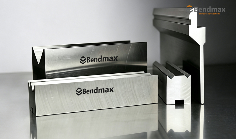
    Standard Press Brake Punch: The Versatile Foundation of Everyday Bending Built for High Bending Loads, Reliable Production and Versatile Sheet Metal Forming In previous articles on the Bendmax Blog, we have shared many articles about press brake solutions, tooling applications and product comparisons. These articles focus on specific bending challenges and practical solutions. When learning about press brake tooling, it is easy to find scattered pieces of information — a punch profile in one place, a die selection guide somewhere else, and an application example on another page. What is often missing is a clear and systematic understanding of the common tools used in press brake bending. That is why we are introducing our upcoming Common Press Brake Tools Series. In this series, we will introduce common press brake punches, dies and tooling accessories one by one, helping you build a more complete understanding of how these tools work and why different designs exist. From the perspective of a technical engineer, we will explore the design principles, functions, working characteristics and typical applications of each tool. More importantly, we will look at the engineering questions behind the tooling: Why are some punches straight while others have a gooseneck design? Why are V-dies available with different V-openings? When should you choose a Standard Punch instead of a Gooseneck Punch? And what should you do when standard tooling cannot form the workpiece you need? Rather than simply listing product specifications, we hope to explain why a tool is designed this way, what problem it is intended to solve, how it works during the bending process, and when choosing it is the right decision. We hope this series can become a practical reference for people who are new to the press brake tooling industry — whether you are a machine operator, tooling buyer, sales engineer, designer, fabricator, or simply someone who is starting to learn how press brake tooling works. But this series is not intended to be a one-way technical guide. We believe that real tooling knowledge comes from questions, applications and practical bending experience. If you have any questions about punches or dies, are unsure which tooling system is suitable for your press brake, or are trying to bend a particular workpiece but are not sure how to form it, feel free to get in touch with us. You can provide your drawing, dimensions, material, thickness, bending angle and other information, or simply describe the problem you are facing. We are happy to discuss different tooling options with you and explore a practical solution. Because the best tooling solution does not always start with a product number. Sometimes, it starts with a question. So welcome to the Bendmax Common Press Brake Tools Series: Start with Strength When selecting a press brake punch, many bending jobs do not require a complicated tool. They need something strong, stable and reliable. That is where the Heavy-Duty Standard Punch comes in. As one of the most widely used upper tools for press brake bending, the Standard Punch is designed around a simple engineering principle: provide a robust working geometry that can handle demanding bending loads while remaining versatile enough for everyday production. For general sheet metal bending, this combination of strength, stability and flexibility makes the Standard Punch an important foundation of a modern press brake tooling system. But strength is not the answer to every bending problem. As workpieces become deeper, profiles become more complex and return flanges move further around the punch, another problem begins to appear: There may simply not be enough space around the punch. And that leads to the next question in our tooling series: What happens when the Standard Punch runs out of space? The answer is not always a stronger punch. Sometimes, the answer is a different geometry. When Standard Punches Run Out of Space, Gooseneck Punches Make Room. 1. What Is a Standard Press Brake Punch? A Standard Punch is the upper tool installed on a press brake to form sheet metal against a lower V-die. During bending, the punch moves downward and forces the workpiece into the die opening. In air bending, the sheet is supported by the shoulders of the V-die while the punch controls the bend position and forming depth. The Standard Punch is designed for a broad range of common bending operations, including: General 90° bending Sheet metal fabrication Plate bending Structural components Cabinets and enclosures Frames and brackets General fabrication work Its relatively robust body provides good resistance to bending loads, while the working nose determines how the force is transferred into the material. In simple terms: The Standard Punch is the reliable all-rounder of the press brake tooling system. 2. Why Does a Standard Punch Need a Strong Body? Press brake bending generates significant forming forces. The punch must withstand these forces repeatedly without excessive deformation, instability or premature wear. A robust punch body helps provide: High structural stability Better resistance to bending loads Consistent tool positioning Long-term dimensional reliability Better suitability for demanding production For specific heavy-duty Bendmax configurations, the tooling can be engineered for high load applications, with some designs reaching up to 1000 kN/m maximum load capacity. However, this figure should always be treated as a product-specific rating, not a universal capacity for every Standard Punch. Actual allowable load depends on factors such as: Punch geometry Material Tool height Cross-section Working radius Bending method Machine capacity Workpiece geometry This is an important distinction when selecting heavy-duty tooling. A stronger-looking punch is not automatically a higher-capacity punch. The complete tool design determines its working load. 3. The Geometry Behind Short-Flange Clearance A Standard Punch is not simply a straight block of hardened steel. Its profile is carefully designed around the bending area. Many Standard Punch designs include a slight concave relief on the inward side while retaining relatively flat outer sides. This geometry creates a useful amount of clearance around the workpiece. For certain short-flange applications, this means the flange can move closer to the punch body without immediate interference. As a result, some applications that appear to require a special Gooseneck Punch may still be completed with an appropriately designed Standard Punch. But there is a limit. The Standard Punch is still fundamentally a relatively solid, robust tool. When the workpiece becomes deeper or the return flange extends further around the punch, the available clearance can become insufficient. That is where tooling geometry becomes more important than simply increasing tool strength. 4. Punch Strength vs. Workpiece Clearance This is one of the most important concepts in press brake tooling selection. Imagine two different problems. Problem A: The bending load is too high The solution may involve: A stronger punch A stronger die A suitable material Larger tooling A higher-capacity machine Problem B: The workpiece physically interferes with the punch The solution is different. Increasing punch strength does not create additional clearance. If the workpiece hits the punch body before the bend is completed, the problem is geometric. You need a tool that provides more space. This distinction can be summarized simply: Strength solves load problems. Geometry solves clearance problems. This is exactly why different punch profiles exist. 5. Why Are 85° Standard Punches Commonly Used? Press brake tooling is available in different punch angles, including configurations around 85°, 86° and 88°. An 85° punch does not mean that the finished workpiece will automatically have an 85° bend. In many air-bending applications, punch and die geometry are selected to provide the required forming clearance and overbend capability for producing angles around 90°. The final bend angle depends on several variables, including: Punch angle Die angle V-die opening Punch nose radius Material type Material thickness Bend depth Material springback Machine control and repeatability Therefore, punch angle should be considered as part of the complete bending system rather than as a single solution for springback. AMADA system Standard Press Brake Punch NO.11.201 AMADA system Standard Press Brake Punch NO.11.230 AMADA system Standard Press Brake Punch NO.10.142 Wila System Type II Standard Punch No.14.020 6. Punch Nose Radius Matters The punch nose radius directly influences the contact between the punch and sheet metal. A smaller radius may be suitable for applications requiring a tighter inside bend, while a larger radius may be needed for thicker material or applications where excessive surface stress must be avoided. The correct radius depends on: Material + Thickness + V-Opening + Required Inside Radius + Bending Method For this reason, Bendmax does not recommend selecting a punch based only on its nominal angle. The complete punch geometry should be matched with the lower die and the actual application. 7. Standard Punch Material: Why Bendmax Uses 42CrMo For Bendmax press brake tooling, 42CrMo is selected for applications requiring a combination of strength, toughness and wear resistance. The material is particularly suitable for demanding press brake tooling because the tool must repeatedly withstand concentrated forming loads. Bendmax also focuses on hardening the areas that experience direct contact and wear. Bendmax Tooling Material Material: 42CrMo Working Radius / Entry Radius Hardness: 54–60 HRC Hardening the working radius and entry radius helps improve resistance to: Wear Surface deformation Repeated contact loading Working-edge damage The goal is not simply to make the entire tool extremely hard. A press brake tool needs the right balance between strength, toughness, hardness and dimensional stability. 8. Precision Grinding: More Than a Smooth Surface Precision grinding is an important part of press brake tooling manufacturing. The working surfaces need to maintain accurate geometry so that different tool segments can work together consistently. Precision machining and grinding help control: Tool dimensions Working radius Tool straightness Parallelism Segment consistency Surface quality Forming Grinding Wheel For segmented tooling, dimensional consistency becomes especially important. A small difference between adjacent segments can influence the contact condition and ultimately affect bending consistency. That is why precision tooling is not simply about producing a tool that “looks accurate.” The geometry must remain accurate where it matters during actual bending. Bendmax Standard Press Brake Toolings Display 9. Can a Standard Punch Handle Thick Material? Yes — when the punch is properly designed and correctly matched to the application. Heavy-duty Standard Punches are commonly selected when the application requires higher bending loads and a robust tool structure. However, tool selection should never be based on material thickness alone. The engineer should also consider: Material strength Material thickness Bend length Inside bend radius V-die opening Required bending force Machine tonnage Tool load capacity Workpiece geometry For demanding applications, the tooling system should always be checked as a complete system. 10. Standard Punch vs. Gooseneck Punch This is where the difference between the two tools becomes very clear. Feature Heavy-Duty Standard Punch Gooseneck Punch Main advantage Strength & versatility Clearance Body design Robust / solid Recessed / open-neck geometry General bending Excellent Good Heavy-duty applications Strong option Application dependent Short-flange clearance Good in suitable designs Excellent Deep boxes Limited by geometry Excellent U-profiles Limited by geometry Excellent Return flanges Application dependent Better access Complex profiles Limited Better suited Main engineering purpose Handle bending loads Prevent tool/workpiece interference The key point is: Gooseneck Punches are not simply “stronger Standard Punches.” They solve a different engineering problem. A Standard Punch focuses heavily on structural strength and general-purpose performance. A Gooseneck Punch changes the upper-tool geometry to create additional clearance. 11. When Should You Choose a Standard Punch? A Standard Punch is usually a strong choice when: The workpiece has conventional geometry There is sufficient clearance around the punch High bending loads are expected General-purpose production is required Short flanges can be formed without interference A robust and economical tooling solution is preferred For many fabrication shops, this makes the Standard Punch the first tool to consider. There is no reason to use a specialized punch when a Standard Punch already provides the required performance. 12. When Is a Standard Punch No Longer the Right Tool? The situation changes when the workpiece begins to interfere with the punch. Typical warning signs include: Deep box sections Narrow U-profiles Long return flanges Deep channels Restricted internal spaces Complex multi-bend profiles Punch-to-workpiece interference At this point, choosing a stronger Standard Punch does not necessarily solve the problem. The question becomes: How can we create more space around the bend? That question leads directly to the next article in the Bendmax series. 13. Why Bendmax Standard Punches? Bendmax designs Standard Punches around three practical requirements: Strength 42CrMo construction provides a strong foundation for demanding bending applications. Precision Precision machining and grinding help maintain consistent tool geometry and dimensional accuracy. Production Efficiency Standard punch profiles are widely used, allowing Bendmax to maintain efficient production and support repeat orders, bulk requirements and practical lead times. For customers purchasing tooling in volume, standardized production also helps improve consistency from one order to the next. 14. The Engineering Lesson The Standard Punch teaches an important lesson about press brake tooling: Do not solve every problem with more strength. A robust tool is valuable when the challenge is bending load. But when the workpiece cannot physically move around the tool, strength is no longer the primary issue. The tool needs a different geometry. And that is where our next tooling solution begins. Continue Your Bending Journey Product DetailsLearn more about this tooling, specifications and compatibility. → Explore the Product: Standard Punch Related SolutionsSee related applications, bending methods and tooling discussions. → Explore Solutions & Discussions Need a Price?Tell us your requirements and get a tooling recommendation and quotation. → Request a Quote: Talk to Our Tooling Engineers Continue the Bendmax Tooling Series Next: When Standard Punches Run Out of Space, Gooseneck Punches Make Room How High-Clearance Gooseneck Geometry Solves the Clearance Problems That Standard Punches Cannot In the next article, we move from strength to clearance and examine how Gooseneck Punches are designed for deep boxes, U-profiles, return flanges and other applications where a conventional Standard Punch can physically interfere with the workpiece.
  • Custom Press Brake Tooling: When Standard Tools Are Not Enough
    Aug 15, 2026
        Custom Press Brake Tooling: When Standard Tools Are Not Enough   Standard press brake tooling can handle a surprisingly wide range of bending jobs. Standard punches, V dies, gooseneck punches, radius tools, and hemming tools cover most everyday applications. But sooner or later, a part comes along that seems to say: “Nice try. Your standard tooling isn't going to work here.” That is usually when custom press brake tooling enters the picture. Custom tooling is not about making something unusual just for the sake of it. It is about designing a tool around a specific part geometry, material, machine, bending sequence, and production requirement when standard tooling can no longer provide the required result.     1. When Do You Actually Need Custom Tooling?   The first question is not “Can you make a custom tool?” The better question is: “Do I really need one?” If a standard punch and die can produce the required bend safely and consistently, there is usually little reason to reinvent the tooling.   Custom tooling becomes worthwhile when standard tools create problems such as:   •   The required bend geometry cannot be achieved •   The flange is too short or too deep •   The workpiece interferes with the standard punch •   Several bends need to be produced in one setup •   A special radius or angle is required •   The part requires offset or Z-bending •   Standard tooling causes marking or deformation •   The production process requires a dedicated forming operation •   Setup time needs to be reduced •   The same special part is produced repeatedly •   The workpiece must be completely free of tool marks.   In other words: If the part is unusual, the tooling may need to be unusual too.       2. Custom Tooling Starts With the Part, Not the Tool   A common mistake is to start the discussion with: “We need a special punch.” That is a little too early. A proper custom tooling design starts with the workpiece. The tooling designer needs to understand: Material Typical information includes: Material grade Thickness Tensile strength Yield strength Surface condition For example, bending 1.5 mm aluminum and 10 mm high-strength steel are obviously not the same job. The tooling geometry, die opening, punch radius, and required bending force can be completely different. Part Geometry Important dimensions include: Overall part dimensions Flange lengths Bend angles Inside bend radii Offset dimensions Holes and cutouts Embossed or formed areas Clearance requirements Even a small feature can determine whether a standard tool will work. Machine Information The tooling must also match the press brake. Important machine parameters include: Press brake manufacturer and model Maximum tonnage Bending length Tooling system Punch holder type Die holder type Maximum tooling height Clamping method Available daylight A beautifully designed custom punch is not very useful if it does not fit the machine.     " For more information, explore our related articles. [ How to Calculate Press Brake Tonnage for Different Tooling (Complete Guide 2026) ] [ How to Select the Right Press Brake Tooling Based on Bending Force ] [ What is Press Brake Tooling? The Ultimate Guide for Manufacturers ]     3. The Most Common Custom Press Brake Tools   Custom Tooling can take many forms. Some are completely unique, while others are essentially modified versions of standard tooling. Here are several common examples.   Custom Punches   A custom punch may be required when a standard punch interferes with the workpiece.   Typical designs include: Extra-deep gooseneck punches Narrow punches Extended punches Special-angle punches Radius punches Offset punches Custom forming punches   Multi-step forming punches     For example, a deep box-shaped workpiece may collide with a standard straight punch. A gooseneck or offset punch can provide the additional clearance needed to complete the bend.   4. Custom Dies   The same principle applies to lower tooling. A standard V die works well for conventional air bending, but special applications may require:   •  Custom V openings •  Multiple V openings •  Asymmetric V dies •  Offset dies •  Radius dies •  U-shaped dies •  Four-way dies •  Adjustable dies •  Forming dies   The die opening is particularly important because it affects the relationship between material thickness, inside radius, bending force, and minimum flange length. For conventional air bending, a commonly used starting point is: V ≈ 6–8 × material thickness But this is not a universal rule. Material strength, desired radius, tooling geometry, and machine capacity all matter. That is exactly why custom tooling should be designed around the actual application rather than simply copying a dimension from a catalog.       5. When One Tool Can Replace Several Tools   Here is one of the biggest advantages of custom tooling: You can sometimes turn several operations into one. Imagine a part that normally requires: Standard bending Tool change Offset bending Tool change Final forming A specially designed forming tool may combine several of these operations into a single setup. That can reduce: Tool change time Machine setup time Operator handling Positioning errors Production variability For high-volume production, even saving 30 seconds per part can become significant. For example, at 500 parts per month: 0.5 min × 500 = 250 minutes That's more than 4 hours of production time saved every month. And that is just from one small improvement.     6. Custom Tooling for Mark-Free Bending   Surface marking is another common reason for going custom. Standard V dies can leave marks on: Stainless steel Aluminum Pre-painted sheet Decorative panels Powder-coated parts High-visibility surfaces If cosmetic quality is important, a custom no-mark or non-marking die may be a better solution. Depending on the application, the tooling may use: Polyurethane inserts Special rollers Replaceable inserts Modified die geometry Low-friction contact surfaces The goal is simple: Bend the sheet without leaving a tool-shaped souvenir behind. This can be especially valuable when the finished component cannot be polished, repainted, or otherwise reworked after bending.     Bendmax Adjustable Rotatable V-die     Bendmax Round-Bar No-Mark Press Brake Die     Bendmax Wing Bending Plus tooling     Bendmax PU Holder and Insert markfree/no-mark dies     Bendmax Protective Film      Bendmax  Rotatable V-die         7. Custom Tooling for Z-Bending and Offset Bending   Offset bending is another classic custom-tooling application. A Z-bend typically requires two parallel bends with a controlled offset between them. You can perform the operation using multiple standard tools, but a dedicated Z-bending tool can sometimes make the process faster and more consistent. The key dimensions are usually: Material thickness Offset height Bend angle Flange length Inside radius Required clearance For repeated production, a dedicated offset tool can make much more sense than repeatedly setting up several standard punches and dies.     8. Hemming and Flattening: Another Special Case   Hemming looks simple. It isn't always. A typical hemming process involves first bending the sheet and then flattening the folded edge. Depending on the material and part design, the process may require: Hemming punches  Flattening punches  Flattening dies Spring-loaded tooling Hydraulic flattening tools Custom forming tools The tooling must provide enough clearance for the pre-bent flange while controlling the final flattened geometry. For production parts with a consistent hemming requirement, custom tooling can help reduce setup complexity and improve repeatability.     9. Materials Matter More Than You Might Think   The same custom tool design cannot necessarily be used for every material. Consider three common materials: Material Typical Characteristics Tooling Consideration Mild Steel Relatively easy to form General-purpose tooling often works Stainless Steel Higher strength and springback Higher force and suitable radii may be required Aluminum Soft surface, lower density Surface protection and suitable radii are important   High-strength steels require even more attention. As material tensile strength increases, the required bending force generally increases as well. Tooling must therefore be checked against the machine's available tonnage and the tooling's allowable load. This is one reason why simply making a tool “stronger” is not the complete answer. Tool geometry, material, heat treatment, and machine capacity all work together.     10. What Is Custom Tooling Made From?   For industrial press brake tooling, material selection is critical. A commonly used material is 42CrMo4 / 42CrMo alloy steel, particularly for tooling that requires a good combination of strength, toughness, and wear resistance. Depending on the application, manufacturers may also use materials such as: C45 42CrMo4 H13 SKD11 Heat treatment is equally important. A custom tool may use: Through hardening Induction hardening Laser hardening Localized hardening Surface treatments For example, a tooling design may use a hardened working area around HRC 54–60, depending on the material grade, manufacturing process, and application requirements. The important point is that hardness should not be considered independently. A tooling component that is extremely hard but too brittle is not necessarily a better tool. Strength + toughness + wear resistance = the real goal.     11. Custom Does Not Mean “Made From Scratch Every Time”   This is worth mentioning. A custom tool does not necessarily mean designing every dimension from zero. In many cases, the best solution is a modified standard tool. For example: Standard punch + modified nose radius or Standard V die + custom insert or Standard holder + custom forming section This approach can reduce manufacturing time and cost while still solving the customer's specific bending problem. It is often a smarter solution than designing a completely new tooling system.       12. How Custom Tooling Is Designed   A professional custom tooling project normally follows a process something like this: Step 1 — Understand the Application Start with the part drawing, material, thickness, bend requirements, and production volume. Step 2 — Check the Machine Confirm the press brake model, tonnage, tooling interface, clamping system, and available working height. Step 3 — Analyze the Bending Process Determine the bending sequence, required V opening, punch geometry, inside radius, clearance, and estimated bending force. Step 4 — Develop the Tool Design CAD modeling can be used to check: Workpiece clearance Tool interference Forming geometry Tool strength Machine compatibility For more complex applications, FEA (Finite Element Analysis) can also be used to evaluate stress distribution and deformation. Step 5 — Manufacture and Heat Treat The tool is machined, heat treated, ground, and finished according to the required tolerances. Step 6 — Test the Tool The final step is not simply: “Looks good. Ship it.” The tooling should be tested against the intended application whenever practical. The final goal is a tool that works on the actual machine with the actual material and actual part geometry.         Related Articles " [  How to Select the Right Press Brake Tooling Based on Bending Force  ]             [  Why Does Bendmax Focus on Strict Process Control During Press Brake Tooling Production?  ]       13. How Much Does Custom Tooling Cost?   There is no universal price. A simple modified punch may cost only slightly more than a standard tool. A large, multi-stage forming tool can be significantly more expensive. Cost depends on factors such as: Tool size Tool material Geometry complexity Machining requirements Heat treatment Grinding tolerance Surface treatment Quantity Testing requirements But the purchase price should not be the only number you look at. Think about the total production cost. If a $500 custom tool eliminates several setup operations and saves 10 minutes per batch, its value can be much higher than its purchase price suggests. That is why custom tooling should be evaluated based on ROI, not just unit price.       14. When Custom Tooling Is Probably Not Worth It   Custom tooling isn't always the answer. If you only need to produce 10 parts once, spending heavily on a dedicated forming tool may not make economic sense. A standard punch and die might be perfectly adequate. Custom tooling becomes more attractive when: The part is produced repeatedly Setup time is significant Standard tools cannot achieve the geometry Quality requirements are high Labor costs are significant Multiple operations can be combined Tooling needs to remain consistent across production runs In short: If you bend it once, standard tooling may win.If you bend it 10,000 times, the calculation changes.     15. What Information Should You Send Your Tooling Manufacturer?   If you want a custom tooling quotation, don't just send: “I need a special punch.” That leaves a lot of room for guessing. A much better starting package includes: 1. Part drawing Preferably a PDF, DXF, or 3D CAD file. 2. Material For example: S235, S355, stainless steel 304, aluminum 5052, etc. 3. Material thickness For example: 2.0 mm, 3.0 mm, 6.0 mm. 4. Bend requirements Include angle, radius, flange length, offset, and other critical dimensions. 5. Press brake information Machine manufacturer, model, tonnage, and bending length. 6. Tooling system European/Promecam, American, Trumpf, WILA, Amada, or another interface. 7. Production requirements Tell the manufacturer whether you need 5 pieces, 500 pieces, or 50,000 pieces. That last number can significantly influence the best tooling solution.     16. Custom Tooling Is Really About Solving a Production Problem     The best custom tooling isn't necessarily the most complicated one. Sometimes it is a sophisticated multi-stage forming tool. Sometimes it is simply a modified punch with 5 mm more clearance. Sometimes a custom insert solves the problem. And sometimes, after looking at the application, the best answer is: “You don't actually need custom tooling. This standard tool will do the job.” That's exactly what you want from a tooling manufacturer. The goal isn't to sell you the most complicated tool. The goal is to find the simplest, safest, and most economical tooling solution that produces the required part consistently.       Standard press brake tooling is the starting point for most bending applications. But when your part geometry gets complicated, production volumes increase, surface quality becomes critical, or standard tools simply cannot provide enough clearance, custom press brake tooling can turn a frustrating bending operation into a much cleaner process. At Bendmax, custom tooling can be developed for different press brake tooling systems, machine interfaces, materials, bend geometries, and production requirements. Whether you need a modified punch, special V die, Z-bending tool, hemming tool, no-mark die, or a completely customized forming solution, the best place to start is not with the tool. Start with the part. Send the drawing, material, thickness, machine information, and bending requirements. We'll work backward from the finished part to the tooling that makes it happen.  
  • European vs American Style Press Brake Tooling: Which One Is Right for Your Press Brake?
    Aug 14, 2026
        European vs American Style Press Brake Tooling Which One Is Right for Your Press Brake?     If you are buying press brake tooling, sooner or later you will run into the same question: European style or American style? At first glance, they may look like two different ways of making essentially the same punch and die. But the differences are actually built into the tooling geometry, clamping method, load transfer, and even the way operators set up a press brake. And no, one is not automatically “better” than the other. The right choice depends on your press brake, your existing tooling system, and how you actually use the machine.       1. First Things First: What Is the Difference? The easiest way to tell the two systems apart is to look at the punch tang and clamping method. European Style Tooling European-style tooling, commonly associated with Promecam-style tooling, uses a relatively narrow tang, typically around 13 mm, with a safety groove or locking feature,For more information, see our [European-style press brake tooling] range. The punch is normally installed into a dedicated holder and can be used with quick-clamping, hydraulic, or mechanical clamping systems. Segmented tooling is also very common. This design is particularly popular on modern CNC press brakes because operators can change tools quickly and combine different punch and die sections for different part lengths. American Style Tooling American-style tooling is the more traditional North American approach. Our [American-style press brake tooling] is designed for machines using this traditional tooling interface. A common reference dimension is a 1/2 in. (12.7 mm) tang, with the punch secured by a mechanical clamping arrangement, set screws, bolts, or a compatible holder depending on the specific tooling design. It is straightforward, robust, and widely used on conventional and older press brakes. So, in simple terms: European = modular + quick change + precision-oriented American = traditional + robust + straightforward But there is a little more to the story.     2. European vs American Tooling: Quick Comparison Feature European Style American Style Typical punch tang Approx. 13 mm Approx. 12.7 mm / 1/2 in. Clamping Quick clamp / hydraulic / mechanical Mainly mechanical Tool change Fast Relatively slower Segmented tooling Very common Available, but less characteristic Tool geometry Slim and highly modular Traditional and robust Typical application CNC, high-mix production General fabrication, conventional brakes Initial tooling cost Usually higher Usually lower Setup flexibility Excellent Good Automation compatibility Excellent Depends on machine/system Best suited for Fast setup & repeatability Simplicity & cost efficiency   One important warning: “European style” and “American style” are not universal dimensions. Different manufacturers and machine models can use proprietary interfaces. Always check the actual punch profile, tang, holder, working height, and clamping system before ordering. A 13 mm tang that “looks close enough” to a 1/2-inch tang is not a compatibility standard.     3. Why Does the Clamping System Matter So Much? This is where things get interesting. A press brake can have hundreds of tons of force available, but that force still has to travel through the ram → holder → punch → sheet → die → lower beam. The tooling interface controls how the punch is located and retained during this process, while a suitable [press brake clamping system] can make tool changes faster and more consistent. With many traditional American-style systems, the operator manually positions the tooling and secures it using the machine's mechanical clamping arrangement. European-style tooling typically uses an offset tang and dedicated holder geometry. The locking mechanism helps locate the punch consistently and makes quick tool changes much easier. This is particularly useful when your production looks something like: Part A → change tools → Part B → change tools → Part C → change tools again. If your operator is changing tooling 15 times a day, saving a few minutes per change quickly becomes more important than the price difference between two punches.     4. European Tooling: Where It Really Shines European-style tooling is a strong choice when setup time and repeatability are important. Fast Tool Changes [Segmented press brake tooling] makes it easier to build the exact working length required while reducing the effort required for frequent tool changes. Instead of wrestling with a long, heavy tool every time, operators can handle shorter sections and arrange them as needed. That is a big advantage for high-mix, low-volume production. More Tool Geometry Options European tooling systems commonly offer a wide range of punch profiles, including: Standard punches Gooseneck punches Acute-angle punches Radius punches Sash punches Hemming tools Offset/Z-bending tools Special forming tools The slimmer tooling profile can also make it easier to work around complicated flange geometries. Quick-Clamping Compatibility If your press brake is equipped with a suitable hydraulic or quick-clamping system, European tooling can make setup considerably faster. For shops doing frequent changeovers, this can translate directly into more machine uptime.       5. American Tooling: Why Is It Still So Popular? Because sometimes simple is good. American-style tooling has been used in North American press brake shops for decades. Many operators already know the system, and many machines already have the appropriate holders and tooling. That means you don't necessarily need to redesign your entire setup just to chase a newer tooling standard. American tooling can be particularly attractive when: You already have a large American-style tooling inventory Your press brake is designed around American tooling Tool changes are relatively infrequent You mainly perform standard bending operations Initial tooling cost is an important consideration Your production does not require extensive segmentation In other words, if your current system works well, there may be no reason to change it simply because another tooling system looks more modern.     6. What About Accuracy? This is where marketing claims can sometimes get a little too enthusiastic. European precision tooling is often associated with precision grinding, controlled dimensions, and repeatable positioning. Many precision tooling systems are manufactured to tight dimensional tolerances, which helps maintain consistent punch and die geometry. But the tooling is only one part of the equation. Your final bending accuracy also depends on: Press brake frame rigidity Ram and bed parallelism Machine calibration Crowning/deflection compensation Backgauge accuracy Material thickness Material strength Tool wear Correct V-die selection Operator setup So buying a precision-ground punch will not magically turn a poorly calibrated press brake into a precision machine. Good tooling + good machine setup = good bending results.         7. What About Heavy-Duty Bending? This is another area where you should look beyond the tooling label. If you regularly bend thick plate, high-strength steel, or large workpieces, the important questions are: What is the allowable load? How is the load transferred? What is the punch geometry? What is the die opening? Is the holder designed for the required tonnage? For example, selecting a punch simply because it is “European style” or “American style” without checking its allowable load is not a good idea. The tooling system must be matched to the machine's tonnage, tooling load rating, material thickness, bend length, and application.   Perhaps this article can also help you learn more.Duty Press Brake Dies Collection>     8. Which One Should You Choose? Here is the practical answer.   Choose European Style Tooling If: You have a modern CNC press brake You frequently change tooling. You manufacture many different parts. You need segmented punches and dies. You value quick setup and repeatability. You are considering hydraulic or quick clamping. You want a broad range of specialized tooling. For a high-mix fabrication shop, European-style tooling can be a very efficient solution.     Choose American Style Tooling If: Your machine is already configured for American tooling You have a large existing tooling inventory. Your production uses relatively standard tooling. Tool changes are not particularly frequent. You prefer a straightforward mechanical setup. Keeping your existing tooling ecosystem is more economical than changing systems.       9. Don't Forget the Machine Comes First This is probably the most important rule: Choose the tooling system based on the press brake—not the other way around.   Before ordering a new punch or die, check:   Tooling system Punch tang dimensions Holder/clamping configuration Punch height Die dimensions Working length Maximum allowable load Required bend angle and radius Machine tonnage Existing tooling inventory ... And don't rely on the machine brand alone.     A machine manufactured in Europe does not automatically mean it uses every type of European tooling. Likewise, an American-built press brake may use a specific proprietary or compatible tooling system. The interface is what matters. Not sure which tooling system or V-die opening is right for your application? Our [What is Press Brake Tooling? The Ultimate Guide for Manufacturers] explains the key factors to consider before ordering. For more information on heavy-duty sheet metal bending, see our guide: [Matching Tooling to Machine Capability].     10. So… European or American? There is no boxing match here. European tooling isn't automatically better. American tooling isn't automatically old-fashioned. They were simply designed around different approaches to clamping, force transfer, tool geometry, and production workflow. If your shop values quick changeovers, modular tooling, precision, and production flexibility, European-style tooling is usually the more attractive choice. If your priority is compatibility, simplicity, durability, and making the most of an existing American-style setup, American tooling can be an excellent choice. And if you're replacing tooling for an existing machine, the best answer is often much less exciting: Buy the tooling that actually fits your press brake. Because the most expensive press brake tooling in the world is still useless if it doesn't fit the machine.     Think Beyond “European vs American”   At Bendmax, we work with different [press brake tooling systems], including European/Promecam-style, American-style, Trumpf-style, WILA-style, Amada-style, and customized tooling. The right tooling isn't simply the one with the most impressive specifications. It is the one that matches your machine, material, bending process, production volume, and existing setup. So before placing an order, send us your machine model, tooling drawing or photos, punch/die dimensions, and bending requirements. We'll help you identify the right tooling system first—because guessing the interface is a much more expensive hobby.    
  • Precision Bystronic Press Brake Tooling Engineered for Maximum Bending Performance
    Jun 05, 2026
    Precision Bystronic Press Brake Tooling Engineered for Maximum Bending Performance If you've invested in a Bystronic press brake, you already understand the value of precision. Modern Bystronic machines are built to deliver exceptional bending accuracy, repeatability, and productivity. But from our experience working with fabricators around the world, even the most advanced machine can only perform as well as the tooling installed on it.   At Bendmax, we spend a lot of time talking with production managers, shop owners, and bending operators. One topic comes up again and again: "How can we get more consistent bends while reducing setup time and tooling costs?" The answer often starts with the tooling. Many standard press brake tools on the market are manufactured with loose tolerances. They may work for basic bending tasks, but when you're trying to hold tight angles, maintain consistent dimensions across long parts, or run automated production cells, small tooling variations quickly become big production problems. That's why we manufacture our Bystronic-style press brake tooling to extremely tight tolerances. Critical dimensions are precision ground to within ±0.01 mm, allowing different tool segments to be mixed and matched while maintaining uniform bending quality across the entire machine length. For fabricators producing electrical enclosures, architectural panels, automotive components, or precision sheet metal parts, this consistency makes a noticeable difference every day.   Another question we often hear is whether premium tooling really lasts longer. In our experience, material selection is just as important as machining accuracy. Bendmax tooling is produced from high-quality 42CrMo alloy steel and undergoes advanced heat treatment processes to improve wear resistance and structural stability. The result is tooling that maintains accuracy longer, resists deformation under heavy loads, and continues performing reliably through years of production. Of course, today's Bystronic press brakes are far more advanced than the machines many shops were using ten years ago. Modern RFA systems incorporate sophisticated crowning technology, intelligent angle correction, and increasingly automated production workflows. These machines are capable of remarkable precision, but they also place higher demands on tooling. Using low-quality or inconsistent tooling can prevent operators from fully benefiting from the capabilities they've invested in.     This is one reason we've continued expanding our Bystronic tooling range. Whether customers need standard punches and dies, gooseneck punches, hemming tools, radius tooling, adjustable dies, or fully custom bending solutions, our goal is simple: help fabricators achieve better bending results with less trial-and-error on the shop floor.   One thing we're particularly proud of is the variety of tooling solutions we can offer. Some customers come to us looking for conventional press brake tooling for general fabrication. Others need precision-ground tooling for aerospace, medical, or high-end enclosure manufacturing. Increasingly, we're also supporting customers who need custom tooling designed around specific parts, materials, or production challenges. Every fabrication shop is different, and tooling should reflect that reality. Over the years, we've learned that the most successful bending operations aren't necessarily the ones with the biggest machines. They're the shops that understand the relationship between machine, tooling, material, and operator. When those four elements work together, productivity improves, scrap decreases, and profitability follows. That's the philosophy behind Bendmax.     We don't simply manufacture press brake tooling. We work with fabricators to help them get more value from their equipment, improve bending consistency, and solve real production challenges. Whether you're operating a single Bystronic press brake or managing a fully automated bending department, choosing the right tooling can have a significant impact on your results. And if you're wondering whether your current tooling is allowing your machine to perform at its full potential, that's a conversation we're always happy to have. Because in sheet metal bending, precision doesn't start with the machine—it starts with the tooling.     Related articles you might be interested in: "Quality Issues Drive Customers Back to Bendmax"   "Common Press Brake Tooling Standards and Interface Analysis" "Angle Inconsistency in Long-Part Bending? Bendmax Manual Crowning System Solves Press Brake Deflection Accurately"      
  • U Die vs V Die: Which Press Brake Die Is Better for Sheet Metal Bending?
    May 25, 2026
    U Die vs V Die: Which Press Brake Die Is Better for Sheet Metal Bending? In modern sheet metal fabrication, selecting the correct press brake tooling is just as important as choosing the right bending machine. Among all lower tooling options, V dies and U dies are the two most commonly used solutions in press brake bending operations. Although both are designed for bending sheet metal, their structures, applications, bending performance, and forming capabilities are very different. Many manufacturers often face the same question: Should this part be bent with a V die or a U die? In some situations, a standard V die can replace a U die and reduce tooling costs. However, in other cases, using a V die instead of a U die may lead to interference, deformation, poor angle consistency, or even bending failure. This article explains the differences between press brake U dies and V dies, including: Tooling classifications Structural differences Main advantages Typical applications When a V die can replace a U die When a U die is absolutely necessary If you are involved in sheet metal bending, CNC press brake tooling selection, or box bending production, this guide will help you choose the right tooling solution. Understanding V Dies in Press Brake Tooling A V die is the most widely used lower die in press brake bending.The working groove is designed in a V shape and is mainly used for standard air bending and bottom bending operations. Because of its versatility and lower production cost, the V die has become the standard tooling solution for most sheet metal fabrication shops. Common Types of V Dies Single V Die The Single V Die contains one V-opening and is commonly used for standard sheet metal bending applications. Typical applications include: 90-degree bending Air bending Stainless steel bending Mild steel fabrication General-purpose forming Main Advantages: Simple structure Fast setup Low tooling cost High bending accuracy Suitable for automated production Single V dies are ideal for high-efficiency CNC press brake operations. Wila-System 86° H100 Single V Die NO.29336 Customized Hardened Bending V Die/ Lower Tool Press Brake Heavy Duty Amada-system Large V Die 80° for Thick Plate Bending LVD System 30° R1.2 V12 H130 NO.26253 High Precision Press Brake V Die Double V Die A Double V Die includes two V-openings with different sizes. This design allows operators to process different material thicknesses without changing tooling frequently. Advantages: Reduces tooling setup time Improves production flexibility Saves tooling inventory space Double V dies are widely used in medium and large fabrication factories. Amada System Press Brake 2V Die NO.20.347 85° V12/V20 Double V Die for Light-Gauge Precision Bending Amada-system Press Brake 2V-Die NO.20.820 85° Dual V 32mm/40mm with Upper and Lower V-openings Multi-V Die A Multi-V Die integrates multiple V openings into one die body. It is especially suitable for: Flexible manufacturing Multi-product production lines Automated bending systems Benefits: Fast job switching Lower tooling investment Improved production efficiency Amada-system Press Brake 4-Way V Die NO.28.820 Universal Multi-V Block 20-70mm Radius V Die A Radius V Die features a rounded groove bottom instead of a sharp V bottom. It is commonly used for: Larger bend radius requirements Surface protection Reducing marking on stainless steel and aluminum Understanding U Dies in Press Brake Tooling A U die is a deep-channel lower die designed specifically for bending parts with deep flanges or box-shaped structures. Compared with standard V dies, U dies provide significantly more clearance space inside the die opening. This makes them highly suitable for complex bending operations where interference is likely to occur. Common Types of U Dies Standard U Die The standard U die is mainly used for: Box bending Cabinet bending Enclosure fabrication Deep flange forming Features: Deep groove design Increased bending clearance Reduced interference risk Large Opening U Die This type of U die is designed for: Large return flanges Thick sheet metal Large-radius bending applications Advantages: Easier part positioning Better compatibility with oversized workpieces Non-Marking U Die Non-marking U dies usually include: Nylon inserts Polyurethane protection Surface-protective materials These dies are widely used for: Mirror stainless steel Decorative panels Aluminum sheets Painted sheet metal Custom U Dies Custom U dies are specially designed for unique workpiece structures. They are common in industries such as: Elevator manufacturing Kitchen equipment Automotive sheet metal Electrical cabinet production Standard U Die Deep-channel press brake die designed for box bending, deep flanges, and interference-free sheet metal forming. Standard Channel Die Standard channel-style lower die suitable for U-shape bending, enclosure forming, and multi-stage bending operations. Mark-free Channel Dies Non-marking channel dies with surface protection design for stainless steel, aluminum, and decorative sheet metal bending. No-Mark U Die U-shaped lower die with PU or nylon protection to prevent scratches during precision bending applications. Custom U Dies Custom-engineered U dies designed for special profiles, deep box bending, and complex sheet metal forming requirements. Main Differences Between U Dies and V Dies Comparison V Die U Die Tool Structure Narrow V-shaped grooveStandardized structureSuitable for general bending Deep U-shaped cavityLarger internal clearanceDesigned for deep or complex bending Application Range Standard 90° bendsAir bendingHigh-speed productionGeneral sheet metal fabrication Box bendingDeep flange partsReturn bendsMulti-stage bending operations Interference ResistanceThis is one of the biggest differences. When bending deep parts, the workpiece may collide with:• Die shoulders• Die sidewalls• Upper punch structure U dies provide additional internal space that prevents interference during deep bending operations. Advantages between V & U Dies Advantages of V Dies Advantages of U Dies Higher Production Efficiency V dies are easier to install and replace, making them ideal for: CNC press brake automation Robot bending systems Mass production environments Better Clearance for Deep Bending This is the most important advantage of U dies. When bending deep box structures, standard V dies often create interference problems. U dies solve this issue by providing a deeper cavity. Lower Tooling Cost Because of their simpler structure, V dies are more economical than U dies. This reduces: Initial tooling investment Inventory costs Maintenance expenses Better for Box and Cabinet Fabrication Applications include: Electrical cabinets Control boxes Server enclosures Kitchen equipment These products often require multiple deep bends. U dies greatly improve forming stability. Better Compatibility V dies are compatible with most standard press brake tooling systems. For example: European style tooling American tooling WILA systems Trumpf systems Reduced Risk of Surface Damage Many U dies are designed with non-marking protection systems. This is essential for: Decorative stainless steel Aluminum panels Painted surfaces Ideal for Air Bending Modern press brake bending increasingly relies on air bending technology. V dies are the preferred choice because they offer: Flexible angle control Lower tonnage requirements Longer tool life Suitable for Complex Structures U dies are often necessary for: Return bends Closed channels Deep profile bending These structures are difficult or impossible to process with standard V dies. When Can a V Die Replace a U Die? In some bending applications, a V die can successfully replace a U die. This helps reduce tooling costs and improve flexibility. Therefore, the ultimate purpose of introducing their working principles and advantages and disadvantages is to enable us to use them reasonably and effectively in serving our needs. However, several important conditions must be considered. 1. The Flange Height Is Relatively Small If the flange is shallow, interference is less likely to occur. In this case, a standard V die may be sufficient. Common examples include: Small channels Shallow boxes Light return bends 2. A Larger V Opening Is Used Increasing the V-opening size creates more clearance space. This allows some shallow box structures to be bent without a U die. However, larger V openings also produce: Larger inside radius More springback Reduced bending precision 3. Air Bending Is Used Air bending reduces contact between the workpiece and die. This can help avoid interference in certain complex bending operations. As a result, many modern fabrication shops use: Large V dies Air bending methods to reduce the need for specialized U dies. 4. Gooseneck Punches Are Used Sometimes the interference comes from the upper punch instead of the lower die. Using: Gooseneck punches Deep throat punches can allow a standard V die to complete more complex bends. Important Risks When Replacing U Dies with V Dies Although replacing a U die with a V die can reduce tooling costs, it also introduces several risks. Interference Problems If the flange is too deep, the workpiece may collide with the die shoulders. This can cause: Deformation Tool damage Incomplete bending Larger Bend Radius Large V openings increase the inside bend radius. This may affect: Product assembly Dimensional accuracy Appearance consistency Increased Springback Air bending with large V dies usually creates more springback. Additional angle compensation may be required. Surface Marking Standard V dies can easily leave marks on: Stainless steel Aluminum Decorative surfaces In these situations, non-marking U dies are safer. When Can a V Die NOT Replace a U Die? There are several situations where a U die is essential. Deep Box Bending Deep electrical cabinets and enclosure parts usually require U dies because standard V dies do not provide enough clearance. Multi-Stage Bending As more bends are formed, the workpiece structure becomes increasingly complex. U dies provide the space needed for later-stage forming. Large Return Flanges Large flanges significantly increase interference risks. Especially for thick materials, U dies are often necessary. High Cosmetic Surface Requirements For mirror stainless steel or painted sheet metal, U dies with protective inserts provide much better surface protection. Special Forming Applications Applications such as: Hemming Return bends Deep channel forming usually require dedicated U dies. How to Choose the Right Press Brake Die Choose a V Die When: Performing standard bending Prioritizing production efficiency Using automated bending systems Processing general sheet metal parts Choose a U Die When: Bending deep box structures Forming large return flanges Processing complex parts Preventing interference Protecting decorative surfaces In modern press brake bending, neither U dies nor V dies are universally better. Instead: Each tooling type is designed for different bending requirements. V dies are ideal for: Standardized production High-speed manufacturing General-purpose bending U dies are essential for: Deep box bending Complex geometries Interference-sensitive applications High cosmetic requirements Today, many sheet metal manufacturers try to replace U dies with large V dies whenever possible in order to: Reduce tooling costs Improve flexibility Simplify production However, for deep and complex bending applications, U dies remain irreplaceable. The best tooling strategy is usually a balanced combination of: Standard V dies Multi-V dies Deep U dies No-marking U dies This provides the optimal balance between: Bending quality Production efficiency Tooling flexibility Manufacturing cost control Related articles you might be interested in: "Common V-opening Types of Press Brake Dies and Their Applications" "How to Calculate Press Brake Tonnage for Different Tooling (Complete Guide 2026)" "How to Select the Right Press Brake Tooling Based on Bending Force" "What is Press Brake Tooling? The Ultimate Guide for Manufacturers"
  • How to Achieve Mark-Free Bending in Sheet Metal Fabrication
    May 23, 2026
    Exploring Mark-Free Bending in Press Brake Workpieces How to Achieve Mark-Free Bending in Sheet Metal Fabrication The Solutions for No-Marking Press Brake Bending In modern sheet metal fabrication, surface quality is becoming just as important as bending accuracy. Industries such as elevator manufacturing, kitchen equipment, architectural decoration, consumer electronics, and automotive interiors all require flawless surfaces without scratches, pressure marks, or die indentations. However, traditional press brake bending often leaves visible bending marks on stainless steel, aluminum, coated sheets, mirror-finish metals, and painted materials. These defects increase rework costs and reduce product value. To solve this problem and prevent bending marks on sheet metal, manufacturers are increasingly adopting advanced no mark press brake tooling solutions. This article explains the most effective methods for achieving flawless results while maintaining bending precision and productivity. What Causes Bending Marks on Sheet Metal? Before selecting a solution, it is important to understand why bending marks occur. During the bending process, the sheet metal slides and presses against the V die surface under high pressure. Friction, concentrated force, and poor die surface conditions can create: Scratches Pressure lines Surface indentation Coating damage Roller drag marks These problems are especially visible on: Mirror stainless steel Brushed stainless steel Aluminum sheets Galvanized steel Painted or coated materials Decorative sheet metal panels The key to mark-free bending is reducing friction and distributing pressure evenly during forming. 6 Professional Solutions for Mark-Free Bending 1. No-Mark Film and Tensioner Systems One of the simplest methods is using a protective no-mark film between the sheet metal and the lower die. The film acts as a protective barrier that absorbs friction during bending and prevents direct metal-to-metal contact. How It Works A flexible protective foil is inserted between the workpiece and the V die. During bending, the film moves together with the sheet, reducing scratching and indentation. Protective film for bending operations press brake Protective Film Holder and Positioner Key Features Available in different thicknesses Easy to install and replace Low investment cost Suitable for temporary protection Advantages Simple and economical Compatible with most standard V dies Effective for light cosmetic protection Limitations Film wears out quickly Requires frequent replacement May slightly affect angle accuracy in precision bending Typical Applications Decorative stainless steel panels Brushed aluminum sheets Light cosmetic components 2. No-Mark Rotary Dies / Wing-Bend Tools Rotary bending dies are among the most advanced solutions for scratch-free bending. The use of Bendmax Rotabend bottom tools helps reduce marking because the hardened rotor wings rotate during bending instead of dragging across the sheet surface. These dies feature a rotating flap mechanism in the lower die. As the punch presses the sheet into position, the flap rotates to maintain surface contact without sliding friction. Key Points Feature: Polished chrome surface (Ra ≤ 0.4 μm) Advantage: Even force distribution with almost no surface dragging Result: Virtually eliminates bending pressure marks Advantages Excellent cosmetic surface protection Reduced friction during forming Consistent bending angles Suitable for automated production Limitations Higher initial cost than standard dies Typical Applications Stainless steel countertops Elevator panels Decorative architectural products High-end appliance panels Why Rotary Dies Work Better: Traditional V dies create sliding friction. Rotary dies convert sliding movement into rotational movement, significantly reducing surface damage. 3. Nylon Insert Press Brake Dies Nylon insert no-mark dies use replaceable nylon materials embedded into the contact area of the lower die. Because nylon has high elasticity and a very low friction coefficient, it greatly reduces mechanical marks on the sheet surface. Structure: The nylon insert maintains the same V opening geometry as standard steel dies while adding a softer contact surface. Key Features Replaceable nylon inserts Same bending geometry as conventional V dies Low-friction contact surface Advantages Excellent protection for sensitive surfaces Lower tooling cost compared to full polyurethane systems Easy maintenance through insert replacement Limitations Nylon inserts wear faster under heavy tonnage Not ideal for very thick materials Typical Applications Stainless steel decoration Coated sheet metal Aluminum enclosure panels 4. Roller-Type Mark-Free Press Brake Tools Roller-type no-mark (mark-free) dies / Free-mark dies with Roller inside use rotating hard alloy rollers integrated into the lower die. As bending occurs, the rollers rotate synchronously with the sheet movement. This transforms sliding friction into rolling friction, dramatically reducing scratches and pressure marks. Key Points Feature: Rotating alloy rollers on contact surfaces Advantage: Dynamic rolling contact Best For: Ultra-thin sheets below 0.5 mm Advantages Extremely low friction Excellent for precision bending Protects delicate coatings and polished finishes Improves consistency in thin-sheet forming Limitations Higher tooling cost Requires maintenance for roller systems Typical Applications Precision electronics Solar panel frames Thin stainless steel covers Consumer electronics housings 5. Polyurethane Insert Press Brake Tools Polyurethane press brake tooling uses soft elastic inserts to cushion the sheet during bending. These inserts distribute bending pressure evenly and prevent direct hard-contact marking. Soft contact inserts may be made from Polyurethane, Nylon, or Rubber-based materials. Polyurethane inserts are especially suitable for bending radiused profiles and delicate decorative materials. Key Points Feature: Polyurethane insert or spring ejector system Advantage: Fully eliminates pressure marks Result: Uniform bend radius with smooth surface quality Advantages Best surface protection among all no-mark solutions Excellent for soft metals Produces smooth and uniform bend radii Limitations Not suitable for thick heavy-gauge materials Polyurethane inserts eventually deform under high tonnage Typical Applications High-gloss aluminum Mirror-finish stainless steel Smartphone frames Decorative consumer products 6. Customized Mark-Free Press Brake Tooling Custom wiping bending Custom U channel bending Custom channel bending For complex geometries or highly sensitive surfaces, customized no-mark tooling is often the best solution. These tools are specifically designed according to: material type, material thickness, bend radius, surface finish requirements, product geometry, and production volume. Custom tooling can combine: rotary structures, polyurethane inserts, roller systems, special surface coatings, and multi-stage bending structures. Advantages Maximum surface protection Optimized bending accuracy Improved production efficiency Best solution for complex applications Typical Applications Aerospace components Premium architectural panels Automotive decorative trims High-end stainless steel fabrication Main Advantages of Mark-Free Bending Tools Modern no-mark press brake tooling offers significant benefits in manufacturing efficiency, quality control, and cost reduction. 1. Surface Protection Prevents scratches, dents, and pressure marks on sensitive materials. 2. Reduced Rework and Scrap Fewer surface defects mean lower rejection rates and more stable production quality. 3. Wide Material Compatibility Suitable for: Stainless steel, Aluminum, Galvanized steel Painted sheets, Decorative metals 4. Longer Tool Life Replaceable inserts extend the overall service life of the tooling system. 5. Higher Production Efficiency Reduces the need for protective films and secondary polishing operations. How to Choose the Right No-Mark Press Brake Tooling Selecting the correct mark-free bending solution depends on several technical factors. Surface Finish Requirements Different finishes require different levels of protection (Mirror finish, Brushed finish, Painted surfaces, Coated materials). The more sensitive the surface, the softer and smoother the tooling contact must be. Material Thickness and Strength Thicker or high-strength materials require stronger insert systems to maintain angle precision. Soft insert systems may deform under excessive tonnage. Bend Angle and V Opening Proper matching between punch radius, V opening, material thickness, and bending angle is essential for maintaining bend consistency and preventing material deformation. Part Geometry Complex shapes such as deep boxes, large-radius bends, U-shaped profiles, and multi-step bends often require specialized no-mark tooling structures. Production Volume & Budget High-volume production favors durable rotary or roller systems. Small-batch production may benefit from modular insert solutions. Replaceable insert systems usually provide the best balance between initial tooling cost, maintenance expense, and long-term service life. Which Mark-Free Bending Solution Is Best? There is no single solution suitable for every bending application. Solution Surface Protection Durability Cost Best Application No-Mark Film Medium Low Low Temporary protection Rotary Dies Excellent High Medium-High Stainless decorative panels Nylon Inserts Good Medium Medium General cosmetic bending Roller Dies Excellent High High Ultra-thin precision sheets Polyurethane Dies Best Medium-Low Medium Mirror-finish materials Custom Tooling Maximum Depends on design High Complex high-end applications As customer expectations for appearance quality continue to rise, mastering scratch free sheet metal bending is becoming a critical requirement in modern fabrication. Choosing the correct no-mark press brake tooling can: Improve product appearance Reduce production defects Increase bending consistency Lower manufacturing costs Enhance customer satisfaction Whether you are bending stainless steel elevator panels, mirror-finish aluminum, or decorative sheet metal, investing in the right no-mark bending solution will significantly improve both product quality and production efficiency.
  • Common V-opening Types of Press Brake Dies and Their Applications
    May 21, 2026
    A Complete Guide to Single V, Double V, 4-Way and Multi-V Dies     Common V-opening Types of Press Brake Dies and Their Applications   In sheet metal bending operations, many operators are forced to use unsuitable tooling simply because the correct Heavy Duty Press Brake Tooling is not immediately available. Surprisingly, acceptable parts can sometimes still be produced using completely different tooling setups. However, this approach is: Inefficient Difficult to repeat Unstable in quality Harmful to workflow efficiency The best practice in press brake tooling selection should always focus on one simple objective: Producing the highest-quality parts in the shortest possible time. Understanding different types of press brake lower dies is therefore essential for improving productivity, reducing setup time, and ensuring bending consistency.     1. What Is a Press Brake Lower Die? A press brake lower die is the tooling mounted on the bed of the press brake and works together with the punch to form sheet metal. The lower die directly affects: Bend angle Inside radius Surface marking Tonnage requirement Bending precision Production efficiency   Common lower die categories include: Single V Dies Double V Dies 4-Way V Dies Multi-V Dies Adjustable V Dies Radius Dies Flattening Dies No-Mark Dies Press Brake Dies with Polyurethane Pads inside Custom Forming Dies   Single V Dies The Single V Die features one precision-ground V-opening and is widely used for standard air bending applications. It is ideal for small and medium-sized CNC press brake machines requiring high bending accuracy, stable forming performance, and quick setup. With only one V-groove, operators can achieve consistent bending results and easier tooling alignment during production. Single V dies are commonly used for stainless steel, carbon steel, aluminum, and other sheet metal materials.Single V dies are the most traditional and widely used lower dies. Common die angles include 30°, 60°, 85°, 86°, and 90°, suitable for producing bend angles of 90° and above depending on material springback and bending method. Advantages include: High precision Excellent rigidity Stable bending performance Strong resistance to off-center loading Common types include: T-Type Single V Dies L-Type Single V Dies Straight Body Dies High Base Dies Radius V Dies Applications:  Stainless steel bending Carbon steel bending Precision batch production Deep box bending   Straight Body Dies Slot-type lower die Radius V Dies T-Type Single V Dies     Double V Dies  The Double V Die contains two different V-openings on the same die body, allowing operators to switch between groove sizes without changing tooling. This design greatly improves production efficiency and reduces machine downtime during multi-thickness bending operations. It is especially suitable for sheet metal workshops processing different material thicknesses or multiple bend requirements in one production cycle. Double V dies provide flexibility, cost savings, and faster setup compared with single-opening tooling. Common die angles include 30°, 60°, 85°, and 86°, supporting various air bending and bottom bending applications. Examples: V8/V12 V10/V16 V12/V20 They provide excellent flexibility while reducing tooling inventory.   High-Strength Tool Steel Construction Common materials: 42CrMo Cr12MoV Alloy tool steel Advantages: Higher wear resistance Longer service life Better crack resistance   Quick Change Systems Modern double-V dies often include: Self-centering systems Quick clamping interfaces Standardized positioning systems Setup time can be reduced to: One-third of traditional tooling systems. Opposed Double V Press Brake Die Dual V-openings on opposite sides allow quick flipping for different bending requirements and reduced tooling changeover time. Adjacent-Side Double V Die Adjacent side V-openings provide flexible die positioning and quick access for varied flange and profile bending requirements. Symmetrical Inline Double V Die Identical inline V-openings ensure balanced force distribution, improved stability, and extended die service life during production. Multi-Size Inline Double V Die Two different V-openings on the same side provide flexible bending for various sheet thicknesses using one die.       4-Way V Dies The Four V Die is a versatile multi-opening press brake die designed with four different V-grooves on four sides of the tooling body. Operators can rotate the die to quickly select different V-opening sizes for various sheet thicknesses and bending requirements. This tooling is widely used in high-mix sheet metal production environments where flexibility, reduced tooling changes, and efficient machine setup are essential. It is suitable for bending stainless steel, mild steel, galvanized sheets, and aluminum materials.   Four V dies are available in multiple V-opening combinations and angle configurations to support precision bending for different applications and part geometries. Typical combinations: V6 V8 V10 V12 Advantages: Fast tooling changeover Reduced tooling quantity Better automation compatibility           Multi-V Dies The Multi-v Press Brake Lower Die is a highly flexible press brake bottom die designed with multiple V-openings in a single tooling body. It allows operators to quickly select suitable V-groove sizes for different material thicknesses and bending requirements without frequent die changes. This tooling significantly improves setup efficiency, reduces tooling inventory, and increases production flexibility in sheet metal fabrication environments handling diverse bending applications. Multi-V dies are commonly used for air bending stainless steel, carbon steel, aluminum, and galvanized sheet materials. Different V-opening combinations help achieve accurate bending radii, stable angles, and consistent forming quality across various workpieces.   Available in multiple angle configurations such as 30°, 60°, 85°, and 86°, Multi-V dies are ideal for high-efficiency CNC press brake production and multi-purpose bending operations. They are ideal for: Flexible manufacturing Automated production High-mix low-volume production Smart factories       2. Specialized Press Brake Dies Beyond standard V-dies, many Custom Sheet Metal Bending Dies have been developed for complex bending applications. Major examples include: Acute Angle Dies Beading Dies Channel Dies Bend-and-Hem Dies Corrugating Dies Curling Dies Flattening Dies Hemming Dies Rotary Dies Urethane dies Tube Forming Dies Standing Seam Dies Wiping Dies Z-Bend Dies Hinge dies Free-mark dies with Roller inside Adjustable Z-Bend Dies Round Bar Dies Each die is designed to solve specific production challenges while improving efficiency and part consistency.         3. BENDMAX Press Brake Die Solutions BENDMAX Official Website provides: Single V Dies Double V Dies 4-Way Dies Multi-V Dies Radius Dies No-Mark Dies Adjustable V Dies Flattening Dies Custom tooling solutions Compatible with: Amada Trumpf Wila Bystronic LVD European Style American Precision Style 4. V-opening Thoughts Press brake lower dies are far more than simple V-grooves. They directly influence: Product quality Productivity Surface finish Automation compatibility Overall manufacturing efficiency When facing complex applications such as: Hemming Hinge bending Radius bending No-mark bending Box forming professional tooling support becomes essential. This article mainly focuses on press brake lower dies. However, other components are equally important, including: Press Brake Punches Clamping Systems Crowning Systems Press Brake Accessories   You can explore more professional press brake knowledge through related articles on our website.     Click to search for the products you are interested in:  
  • How to Calculate Press Brake Tonnage for Different Tooling (Complete Guide 2026)
    May 06, 2026
    How to Calculate Press Brake Tonnage for Different Tooling  — Tooling Formula & Tonnage Chart     Press brake tonnage is calculated based on material thickness, material strength, die opening, and bending length. For air bending, the standard formula is:   T=1.42×σ×t2VT = \frac{1.42 \times \sigma \times t^2}{V} T=V1.42×σ×t2​ Where: T = tonnage per meter (kN/m) σ = tensile strength of material (N/mm²) t = material thickness (mm) V = die opening (mm) In simple terms: Thicker material requires more tonnage Smaller V opening requires more tonnage Stronger material requires more tonnage This formula is commonly used when selecting: heavy duty press brake dies multi V press brake dies large V opening press brake die       Smaller die openings and thicker materials dramatically increase bending tonnage. Why Press Brake Tonnage Matters Correct tonnage calculation helps manufacturers: Prevent machine overload Avoid tooling breakage Improve bending accuracy Extend tool life Reduce production cost Incorrect tonnage selection can cause: Cracked punches Damaged dies Machine deflection Poor bending angles   Press Brake Tonnage Formula Explained 1. Material Thickness Tonnage increases exponentially with thickness. Example:   Thickness Relative Tonnage 1 mm 1× 2 mm 4× 3 mm 9× 4 mm 16×   Because thickness is squared in the formula. 2. Die Opening (V Opening)     The V opening directly affects tonnage.   A large V opening press brake die reduces bending force and machine load. This is ideal for: aluminum sheets thin sheet metal large radius bending   3. Material Type Different materials require different tonnage. Material Relative Force Mild Steel 1.0× Stainless Steel 1.5× Aluminum 0.5×     Example:If mild steel needs 50 tons, stainless steel may require 75 tons.   Tonnage Differences by Tooling Type Heavy Duty Press Brake Dies     Best for: thick plate bending structural steel high tonnage applications Keywords naturally included: heavy duty press brake dies Characteristics: reinforced body high load capacity smaller V options Advantages: high durability suitable for thick material better load resistance Disadvantage: higher tonnage demand Typical applications: truck chassis construction parts industrial cabinets   Multi V Press Brake Dies     Keywords naturally included: multi V press brake dies Multi V dies contain several V openings in one tool. Benefits: one die for multiple thicknesses reduced setup time lower tooling inventory cost Applications: job shops flexible manufacturing small batch production Example:A single multi V die may include: 16 mm 22 mm 35 mm 50 mm V openings This allows operators to optimize tonnage quickly.   Large V Opening Press Brake Die     Keywords naturally included: large V opening press brake die Large V dies are ideal for: soft materials cosmetic parts no-mark bending Advantages: lower tonnage larger bend radius reduced tool wear Best for: HVAC panels enclosures appliance parts   Example Press Brake Tonnage Calculation Material: Mild steelThickness: 3 mmV opening: 24 mm Formula: T=1.42×450×3224T = \frac{1.42 \times 450 \times 3^2}{24}T=241.42×450×32​ Result: ≈ 24 kN/cm This equals approximately: 240 tons/meter (Actual values vary by machine and tooling geometry.)   Recommended Die Selection Rule A common rule: V opening = 6× to 8× material thickness Examples: Thickness Recommended V Opening 1 mm 6–8 mm 2 mm 12–16 mm 3 mm 18–24 mm 6 mm 36–48 mm     For thick materials, choose heavy duty press brake dies. For flexible production, choose multi V press brake dies. For lower tonnage and smoother bending, choose large V opening press brake die.     Accurate press brake tonnage calculation is essential for safe and efficient bending. Choosing the right tooling matters: ✅ Heavy duty press brake dies for high tonnage and thick plate✅ Multi V press brake dies for flexible production✅ Large V opening press brake die for lower tonnage and larger radius bending At BENDMAX, we supply high-precision press brake tooling designed for: durability accuracy compatibility with major press brake systems Contact us for tooling recommendations and custom bending solutions.   FAQ: Press Brake Tonnage Calculation How do I calculate press brake tonnage? Use this formula: T=1.42×σ×t2VT = \frac{1.42 \times \sigma \times t^2}{V}T=V1.42×σ×t2​ Tonnage depends on: thickness material die opening   Does a larger V opening reduce tonnage? Yes.A larger V opening reduces required bending force but increases bend radius. This is why a large V opening press brake die is used for low-force bending.   What tooling is best for thick plate bending? For thick materials, use heavy duty press brake dies because they offer: higher load capacity better structural strength reduced deformation   Why use multi V press brake dies?       Multi V press brake dies improve efficiency by allowing multiple V openings in one die. Benefits: fewer tool changes lower tooling cost higher flexibility Bendmax provides tonnage reference data for each product, which can be used as a guideline when selecting tooling. You can also contact our engineers for professional assistance.    
  • Why Does Bendmax Focus on Strict Process Control During Press Brake Tooling Production?
    Apr 21, 2026
    Why Does Bendmax Focus on Strict Process Control During Press Brake Tooling Production?   In sheet metal fabrication, press brake tooling quality directly affects bending accuracy, production efficiency, and the surface quality of finished parts. Even when using high-precision press brake machines, poor tooling can lead to inconsistent angles, premature wear, or surface marks on the workpiece. To ensure consistent performance and long service life, Bendmax implements a strict 12-step production process. From raw material selection to final delivery, every stage is carefully controlled to guarantee stable tooling quality and reliable bending results.     Bendmax Press Brake Tooling Production Process (12 Steps) 1. Press Brake Tooling Design     The production process begins with professional tooling design. Bendmax engineers evaluate the customer’s bending requirements, including sheet thickness, material type, bending radius, and forming sequence. Based on these factors, engineers determine whether standard tooling can meet the application or if custom forming tools should be developed to improve bending efficiency and precision.         Fast Engineering Response 15 years of experience Clearly Drawings 24 hours / 6 days Special tools accurately & reliably Step-by-step bending process     2. Raw Material Selection     The durability of press brake tooling begins with the quality of its raw materials. Bendmax uses forged 42CrMo alloy steel (42CrMo4) because of its excellent balance of: high strength strong toughness wear resistance fatigue resistance To ensure material reliability, Bendmax provides material certification from suppliers and third-party testing verification.     3. Body Hardening     After material preparation, the tooling undergoes salt bath quenching and tempering. This controlled heat treatment process stabilizes the internal structure and brings the tool body hardness to HRC 30–35, ensuring high structural toughness and reducing the risk of cracking under heavy bending loads.     4. CNC Milling     The tooling blanks are then machined using high-precision CNC machining centers. This process ensures: accurate punch and die profiles repeatable production across batches tight dimensional tolerances CNC milling forms the fundamental geometry required for further finishing operations.     5. Surface Deep Hardening     The working areas of the tooling undergo induction hardening. During this process, the surface is heated to 850–950°C, significantly improving wear resistance. The working surface hardness reaches HRC 54–60, allowing the tooling to withstand repeated bending cycles without excessive wear.       6. Sandblasting     After heat treatment, the tooling surface is treated through sandblasting. This process provides several advantages: improved resistance to surface scratches reduced internal machining stress better long-term stability It also creates a uniform surface finish similar to that used by leading international tooling manufacturers.     7. Precision CNC Grinding     Grinding is one of the most critical stages in press brake tooling production. Bendmax uses CNC grinding machines to finish key tooling surfaces with high accuracy, ensuring precise: bending angles radii heights V-groove geometry This precision directly determines the consistency of bending results.           8. Segmented Tool Cutting     To improve flexibility in bending operations, many tools are produced as segmented tooling sets. Standard configurations include: 835 mm solid tools 415 mm solid tools segmented tooling combinations Segmented tools allow operators to quickly assemble tooling lengths for different bending applications.                     ——Common European Segmented Tooling Length     9. Quality Inspection     Strict quality control ensures the accuracy and reliability of every tool. Bendmax uses professional inspection equipment such as: Coordinate Measuring Machines (CMM) Contour measuring instruments Height gauges Straightness measuring tools Finished tooling can achieve dimensional tolerances of ±0.02 mm, ensuring stable bending precision.   (The staff conducting the inspection)     10. Laser Marking     Each tool is marked using laser engraving to clearly display key parameters, including: tooling code bending angle radius tonnage capacity length This allows operators to easily identify and select the correct tooling during production.     11. Protective Packaging     Bendmax uses multi-layer packaging protection to ensure safe transportation: Anti-rust oil coating Greaseproof paper wrapping Individual plastic sealing Carton packaging Reinforced wooden crates This prevents rust, damage, or deformation during shipping.               ——Packaging Process Diagram       12. Delivery and Logistics     Bendmax offers efficient global delivery solutions based on customer requirements. Typical delivery times: Standard tooling: 3–5 days Customized tooling: 20–25 days The company also assists customers in selecting the most economical and reliable transportation methods.       Why Strict Process Control Is Critical for Press Brake Tooling Press brake tooling operates under high pressure and repeated forming cycles. Without proper process control, tooling may suffer from problems such as: uneven hardness dimensional deviation premature wear tool cracking unstable bending angles By implementing a strictly controlled production process, Bendmax ensures consistent material quality, precise geometry, and reliable performance.     Bendmax Press Brake Tooling – Reliable Quality for Global Manufacturers Through strict engineering standards and controlled manufacturing processes, Bendmax provides high-precision press brake punches and dies for global sheet metal fabrication industries. The result is tooling that delivers:   consistent bending accuracy longer service life improved production efficiency reduced maintenance costs      
  • Bendmax Standard Press Brake Tooling In Stable Stock
    Apr 21, 2026
    Bendmax Standard Press Brake Tooling In Stable Stock High Quality Punches & Dies for Precision Bending     Bendmax standard press brake tooling provides reliable performance, precise bending quality, and long-term durability for global sheet metal fabrication.    Our standard tooling range includes the most widely used press brake punches—such as straight punches, acute punches, gooseneck punches, hemming punches, and radius punches—covering common bending needs from simple air bending to box forming and hemming operations.     The Standard V-Dies for Press Brakes selection includes the industry’s popular single-V models in 85°, 88°, 30°, and 60°, offering stable support and accurate bending angles for a wide range of materials and thicknesses.     All Bendmax punches and dies are manufactured from premium 42CrMo alloy steel and undergo full quenching and hardening treatment to ensure superior strength, toughness, and wear resistance.   To further enhance durability, the tool edges and sheet-contact areas can be laser-hardened or coated with a protective black finish, significantly improving surface hardness and extending service life even under continuous production.   To guarantee dimensional accuracy and consistency, every piece of tooling passes through strict quality control using height gauges, contour measuring instruments, and coordinate measuring machines capable of inspecting geometry, straightness, angle precision, radius tolerances, and overall hardness.     This metrology-based inspection process ensures that each standard tool meets international machining standards and integrates seamlessly with press brakes worldwide. Bendmax standard tooling is competitively priced and stocked in large quantities, enabling fast delivery and minimizing customer downtime.   As actual punch models, die angles, and inventory levels may change due to ongoing product updates and sales adjustments, we encourage customers to contact us directly for the latest specifications and stock information.   Beyond high-quality products, Bendmax provides full-chain customer service covering consultation, technical design, manufacturing, installation, calibration, training, spare parts, and global after-sales support for tooling, cylinders, clamping systems, crowning units, and accessories. Customer satisfaction remains our top priority, and we offer 24/7 technical support, flexible customization options, and fast global shipping to ensure reliable performance in every bending application.   Bendmax standard press brake tooling is designed to deliver consistent angles, stable results, and long-lasting value, making it a trusted choice for workshops, OEMs, and Sheet-Metal Manufacturers worldwide.   Bendmax Tips:Due to ongoing product updates and sales adjustments, the available punch types, die angles, and stock levels may vary. Please contact us directly for the latest specifications and inventory information.
1 2
Leave A Message
If you are interested in our products and want to know more details,please leave a message here,we will reply you as soon as we can.
submit

leave a message

leave a message
If you are interested in our products and want to know more details,please leave a message here,we will reply you as soon as we can.
submit

home

products

WhatsApp

Contact Us