



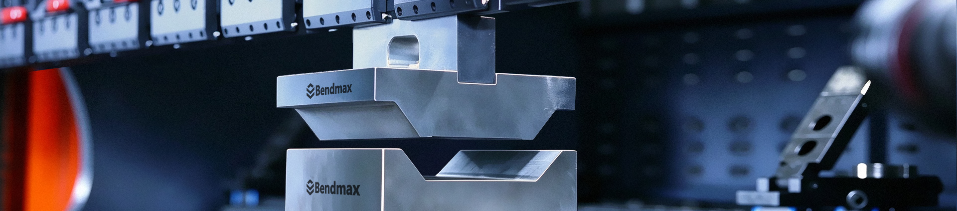
When customers come to us with a special bending requirement, I always start by looking closely at the finished part drawing. The key is not simply to find a punch and die that can bend the material into a U shape, but to understand every detail that the finished component must reproduce.
That was the main consideration behind this custom tooling solution.
The workpiece has a U-shaped cross-section with a series of small protrusions distributed along its bottom. These repeated features make the application different from conventional U-shaped bending. The overall profile and the small bottom details must be formed together, so the tooling needs to be designed around the actual geometry of the part.
Rather than adapting a standard tool to a requirement it was not designed for, we developed a dedicated upper punch and lower die to match the customer's drawing.
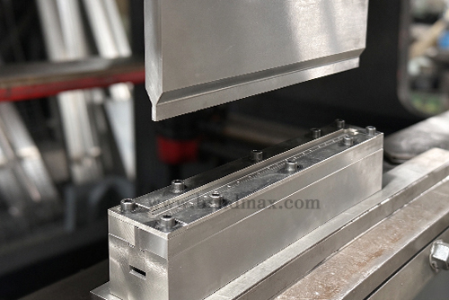
BENDMAX CUSTOM U-Shaped Tool
The most important part of this design is the relationship between the upper punch and the lower die.
Along the length of the upper punch, small forming projections are repeated at specified positions. The lower die contains corresponding grooves. During forming, these complementary profiles work together to create the required protrusions on the bottom of the U-shaped component.
This arrangement requires careful attention to the dimensions, spacing, and alignment of the repeated features. A design that looks correct in a drawing is not enough; the upper and lower profiles must also work together under actual forming conditions.
When developing special tooling, I pay particular attention to these interfaces. The overall tool shape may be straightforward, but the details that determine the final workpiece geometry are often where the real engineering work lies.
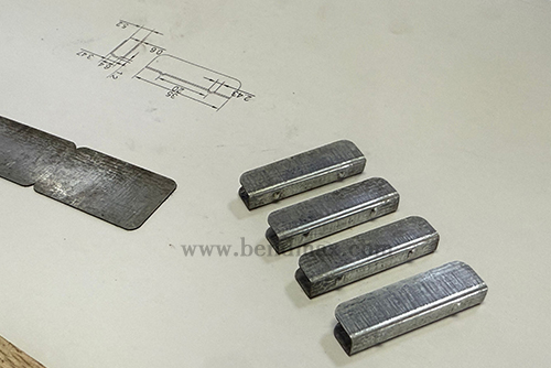
Customer Drawing and Part Dimensions
Before moving into production, we reviewed the tooling structure against the customer's drawing.
The main focus was to check the correspondence between the punch projections and die grooves, as well as the overall forming geometry and the space available for the workpiece. We also considered the clearance required for the intended material and forming process.
This stage is best described as tooling design verification, rather than finite element simulation. Its purpose is to review the proposed geometry and identify potential design conflicts before the tools are manufactured.
For custom tooling, this review is an important step in reducing avoidable adjustments later. The more clearly the part requirements are translated into the tooling structure, the more effectively the design can be evaluated during trial bending.
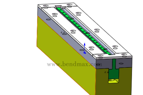
Custom Punch and Die Design
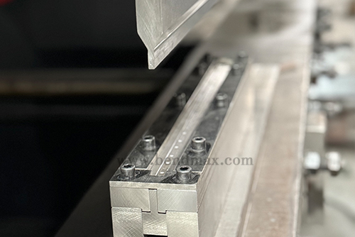 |
From the Drawing to the Actual ToolingOnce the design had been reviewed, the upper punch and lower die were manufactured according to the specified profiles. For tooling with repeated forming features, consistency along the tool length matters. The projections and grooves need to follow the intended dimensions and spacing, while the matching surfaces must work together as designed. After manufacturing, the tools were checked before installation on the press brake. This provided an opportunity to verify their dimensional details and matching geometry before evaluating the actual forming result. The purpose of this process is straightforward: the finished tooling must do more than resemble the design. It must be suitable for the intended application. |
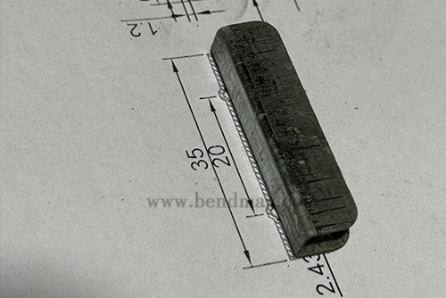 |
Trial Bending: Where the Design Meets RealityNo matter how carefully a special tool is designed, its performance ultimately needs to be checked in practice. After installing the tooling on the press brake, the next step was to evaluate the forming result. We focused on the overall U-shaped profile and, especially, whether the repeated bottom protrusions were formed as intended. Trial bending also helps reveal issues that cannot always be judged from the tool geometry alone. Material properties, machine setup, alignment, and bending parameters can all affect the final component. This is why I regard trial bending as an essential part of custom tooling development. It connects the design work with the actual production conditions and provides a basis for any necessary adjustments. |
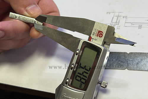
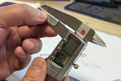
The final step was to inspect the formed component against the customer's drawing.
Using a digital caliper, we checked the relevant dimensions and evaluated the finished profile. Particular attention was given to the U-shaped section and the dimensions associated with the repeated bottom features.
For me, dimensional inspection is not simply the last item on a production checklist. It is the point at which we compare the original requirement with the actual result. The drawing defines what the part should be; the inspection helps establish whether the finished component meets the agreed requirements.
The acceptance decision must be based on the specified dimensions, tolerances, and inspection criteria rather than appearance alone.
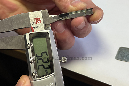
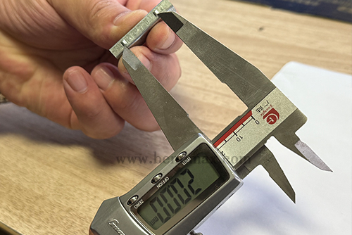
Looking back at this application, the main lesson is that special bending requirements should be approached from the finished part backwards.
A U-shaped component with repeated bottom protrusions requires more than a suitable bending angle. Its tooling must reproduce the overall profile and the local forming details through a coordinated punch-and-die structure.
For us, the work involved understanding the drawing, designing the matching profiles, verifying the tooling structure, manufacturing the tools, and checking the finished component through trial bending and dimensional inspection. Each step served the same purpose: to connect the customer's part requirements with a workable tooling solution.
At Bendmax, this is how we approach custom press brake tooling. We do not begin with a standard tool and expect every application to fit it. We begin with the workpiece, identify the forming challenges, and develop the tooling around the requirements that matter.
 |
|
 Phone: (0086)-15002165198
 Email: jason@bendmax.com
 Wechat: Privacy Policy

 IPv6 network supported
leave a message
Scan to wechat :

Scan to whatsapp :

 English


